Joint Design and Actuation
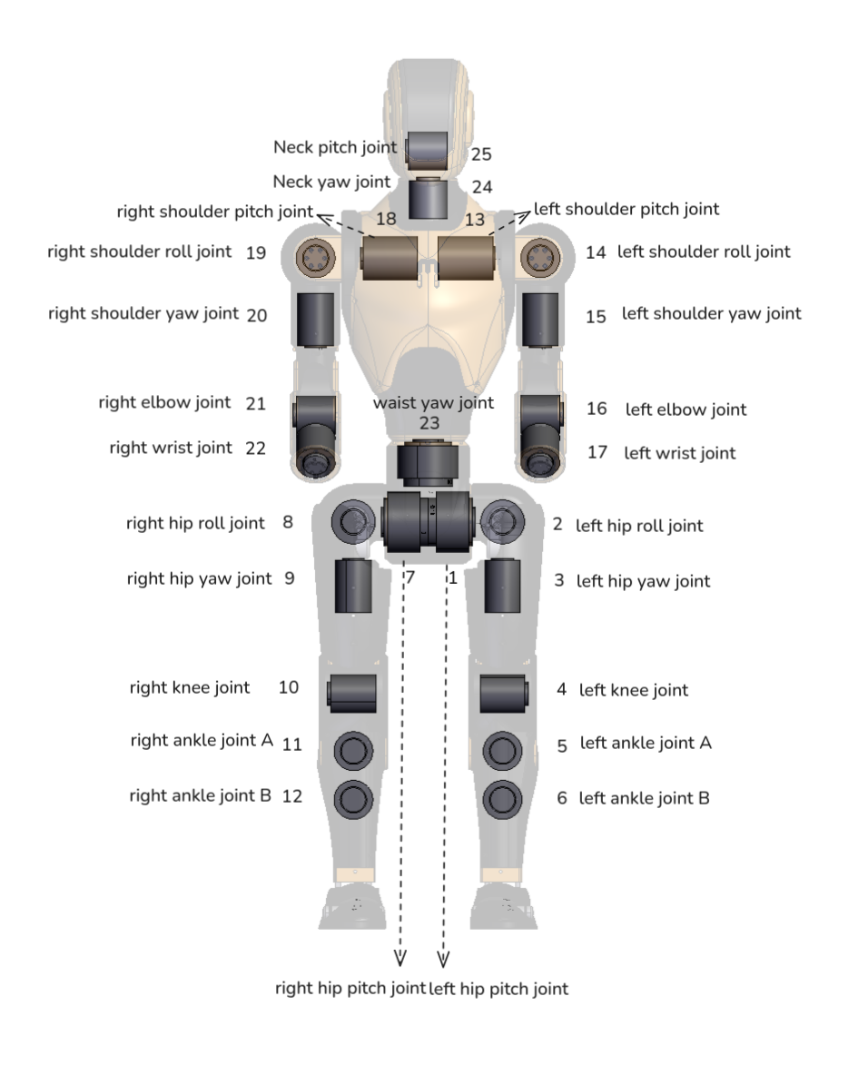
Asimov Full Body is a 25-DOF humanoid robot with 23 actuated DOF and 2 passive toe joints.
12leg joints (6per leg):hip_pitch,hip_roll,hip_yaw,knee,ankle_pitch,ankle_roll1waist joint:waist_yaw10arm joints (5per arm):shoulder_pitch,shoulder_roll,shoulder_yaw,elbow,wrist_yaw2head joints:neck_yaw,neck_pitch2passive toe joints:left_toe_joint,right_toe_joint
For locomotion, we use the 23-DOF body model and lock the two head joints.
This chapter documents joint-level actuation limits and the ankle mechanism model used for design and control.
1. Joint Actuator Specification
The table below maps each actuated joint to its actuator, kinematic limits, and the core actuator-model parameters used for that joint. Passive toe joints are included for completeness and are marked with N/A where actuator-specific values do not apply.
| Motor ID | Joint Name | Actuator ID | Motion Range (rad) | Velocity Limit (rad/s) | Kt | Armature | Rated Torque (Nm) | Peak Torque (Nm) | Static Friction | Dynamic Friction |
|---|---|---|---|---|---|---|---|---|---|---|
| 1 | left_hip_pitch_joint | EC-A6416-P2-25 | -2.09 ~ 1.00 | 12.57 | 2.75 | 0.095625 | 40.0 | 120.0 | 0.70 | 0.050 |
| 2 | left_hip_roll_joint | EC-A5013-H17-100 | -0.79 ~ 0.79 | 3.98 | 7.15 | 0.11 | 30.0 | 90.0 | 0.20 | 0.020 |
| 3 | left_hip_yaw_joint | EC-A3814-H14-107 | -0.79 ~ 0.79 | 5.45 | 5.70 | 0.038 | 20.0 | 60.0 | 0.70 | 0.050 |
| 4 | left_knee_joint | EC-A4315-P2-36 | 0.00 ~ 1.50 | 12.25 | 2.53 | 0.0339552 | 25.0 | 75.0 | 0.70 | 0.020 |
| 5 | left_ankle_pitch_joint | EC-A4310-P2-36 | -0.35 ~ 0.35 | 9.32 | 1.81 | 0.0565056 | 40.0 | 145.4 | 0.40 | 0.015 |
| 6 | left_ankle_roll_joint | EC-A4310-P2-36 | -0.10 ~ 0.10 | 9.32 | 1.81 | 0.0565056 | 17.0 | 57.6 | 0.40 | 0.015 |
| 7 | right_hip_pitch_joint | EC-A6416-P2-25 | -1.00 ~ 2.09 | 12.57 | 2.75 | 0.095625 | 40.0 | 120.0 | 0.70 | 0.050 |
| 8 | right_hip_roll_joint | EC-A5013-H17-100 | -0.79 ~ 0.79 | 3.98 | 7.15 | 0.11 | 30.0 | 90.0 | 0.20 | 0.020 |
| 9 | right_hip_yaw_joint | EC-A3814-H14-107 | -0.79 ~ 0.79 | 5.45 | 5.70 | 0.038 | 20.0 | 60.0 | 0.70 | 0.050 |
| 10 | right_knee_joint | EC-A4315-P2-36 | -1.50 ~ 0.00 | 12.25 | 2.53 | 0.0339552 | 25.0 | 75.0 | 0.70 | 0.020 |
| 11 | right_ankle_pitch_joint | EC-A4310-P2-36 | -0.35 ~ 0.35 | 9.32 | 1.81 | 0.0565056 | 40.0 | 145.4 | 0.40 | 0.015 |
| 12 | right_ankle_roll_joint | EC-A4310-P2-36 | -0.10 ~ 0.10 | 9.32 | 1.81 | 0.0565056 | 17.0 | 57.6 | 0.40 | 0.015 |
| 13 | left_shoulder_pitch_joint | EC-A5013-H17-100 | -3.14 ~ 0.87 | 3.98 | 7.15 | 0.11 | 30.0 | 90.0 | 0.20 | 0.020 |
| 14 | left_shoulder_roll_joint | EC-A4315-P2-36 | -1.57 ~ 0.00 | 12.25 | 2.53 | 0.0339552 | 25.0 | 75.0 | 0.70 | 0.020 |
| 15 | left_shoulder_yaw_joint | EC-A3814-H14-107 | -1.57 ~ 1.57 | 5.45 | 5.70 | 0.038 | 20.0 | 60.0 | 0.70 | 0.050 |
| 16 | left_elbow_joint | EC-A4310-P2-36 | 0.00 ~ 2.44 | 9.32 | 1.81 | 0.0282528 | 12.0 | 36.0 | 0.40 | 0.015 |
| 17 | left_wrist_yaw_joint | EC-A4310-P2-36 | -3.14 ~ 3.14 | 9.32 | 1.81 | 0.0282528 | 12.0 | 36.0 | 0.40 | 0.015 |
| 18 | right_shoulder_pitch_joint | EC-A5013-H17-100 | -0.87 ~ 3.14 | 3.98 | 7.15 | 0.11 | 30.0 | 90.0 | 0.20 | 0.020 |
| 19 | right_shoulder_roll_joint | EC-A4315-P2-36 | 0.00 ~ 1.57 | 12.25 | 2.53 | 0.0339552 | 25.0 | 75.0 | 0.70 | 0.020 |
| 20 | right_shoulder_yaw_joint | EC-A3814-H14-107 | -1.57 ~ 1.57 | 5.45 | 5.70 | 0.038 | 20.0 | 60.0 | 0.70 | 0.050 |
| 21 | right_elbow_joint | EC-A4310-P2-36 | -2.44 ~ 0.00 | 9.32 | 1.81 | 0.0282528 | 12.0 | 36.0 | 0.40 | 0.015 |
| 22 | right_wrist_yaw_joint | EC-A4310-P2-36 | -3.14 ~ 3.14 | 9.32 | 1.81 | 0.0282528 | 12.0 | 36.0 | 0.40 | 0.015 |
| 23 | waist_yaw_joint | EC-A6416-P2-25 | -1.57 ~ 1.57 | 12.57 | 2.75 | 0.095625 | 40.0 | 120.0 | 0.70 | 0.050 |
| 24 | neck_yaw_joint | EC-A4310-P2-36 | -1.57 ~ 1.57 | 9.32 | 1.81 | 0.0282528 | 12.0 | 36.0 | 0.40 | 0.015 |
| 25 | neck_pitch_joint | EC-A4310-P2-36 | -0.79 ~ 0.79 | 9.32 | 1.81 | 0.0282528 | 12.0 | 36.0 | 0.40 | 0.015 |
Motor ID mapping:
Parameter Definitions
Kt: motor torque constant. It maps motor current to output torque:Torque (Nm) = Kt * current. A largerKtmeans more torque is produced per ampere of current.Armature: joint armature can help with stability by adding joint-space inertia and corresponding damping. If a geared actuator is modeled,armaturecan be set to represent the reflected inertia of the motor rotor, wherearmature = JG^2, withGdenoting the ratio of motor angular velocity to output shaft angular velocity, andJdenoting the rotor inertia.Rated Torque: the continuous torque the actuator can sustain without overheating under normal operating conditions.Peak Torque: the short-duration maximum torque the actuator can produce for brief events such as impacts, push-off, or fast recovery motions.Static friction: the torque needed to break the joint free from rest. Measured from a stall test.Dynamic friction: the lower resisting torque once the joint is already moving. Estimated from slow-motion joint tests and fitted into the actuator model.
2. Ankle Parallel Mechanism
Parallel Mechanical Design
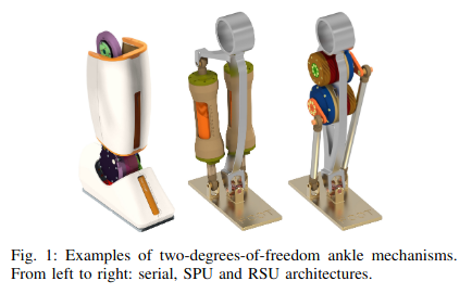 Figure: RSU ankle parallel mechanism
Asimov uses a parallel RSU ankle (Revolute-Spherical-Universal) instead of a simple serial single-DOF ankle. The RSU layout provides two ankle DOFs (pitch and roll) while allowing coupled actuation through two revolute motors.
Kinematic Mapping for the Parallel Mechanism
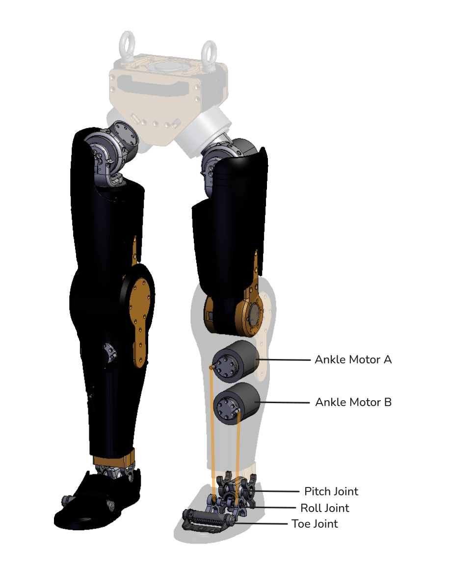 Figure: Ankle joint overview
In simulation, we model the ankle pitch and roll joints as directly actuated at their ideal joint locations to avoid the computational cost of simulating the full parallel mechanism. In hardware, pitch and roll are controlled by moving two endpoints on a straight bar; these endpoints are connected through parallel linkages to ankle motors A and B. Because the ankle pitch and roll joints are not directly actuated in the real system, kinematic mapping is required for sim-to-real policy deployment.
We define the following variables:
theta_p: ankle pitch angle (joint space)theta_r: ankle roll angle (joint space)theta_A: motor A rotation angletheta_B: motor B rotation angler_A,r_B: effective crank/linkage radii of motors A and Br: common radius whenr_A = r_B = rd: distance from the ankle pivot to the bar midpoint linec: distance between the left and right bar endpoints
Assumptions:
- Small-angle approximation is used:
sin(theta) ≈ theta,tan(theta) ≈ theta(angles in radians) - The bar/linkage geometry is rigid and symmetric
r_Aandr_Bare constant effective radii (no compliance, backlash, or slip)- Sign convention is fixed and consistent:
+yis away from the ground,-yis toward the ground- Positive motor/joint rotation directions are predefined and unchanged
- The same derivation frame (right-leg convention) is used when applying the equations
- For simplified forms, assume
r_A = r_B = r
Mapping equations (AB -> PR):
theta_p = (r_A * theta_A - r_B * theta_B) / (2 * d)
theta_p = (theta_A - theta_B) * (r / (2 * d))
theta_r = - (1 / c) * (r_A * theta_A + r_B * theta_B)
theta_r = - (theta_A + theta_B) * (r / c)
Code example:
float right_pitch = (right_A - right_B) / (2.0f * K_PITCH);
float right_roll  = -(right_A + right_B) / (2.0f * K_ROLL);

float left_pitch  = (left_A - left_B) / (2.0f * K_PITCH);
float left_roll = -(left_A + left_B) / (2.0f * K_ROLL);For more information on deriving the ankle mechanism equations, see the ankle mechanism derivation note.
3. Passive toe joints
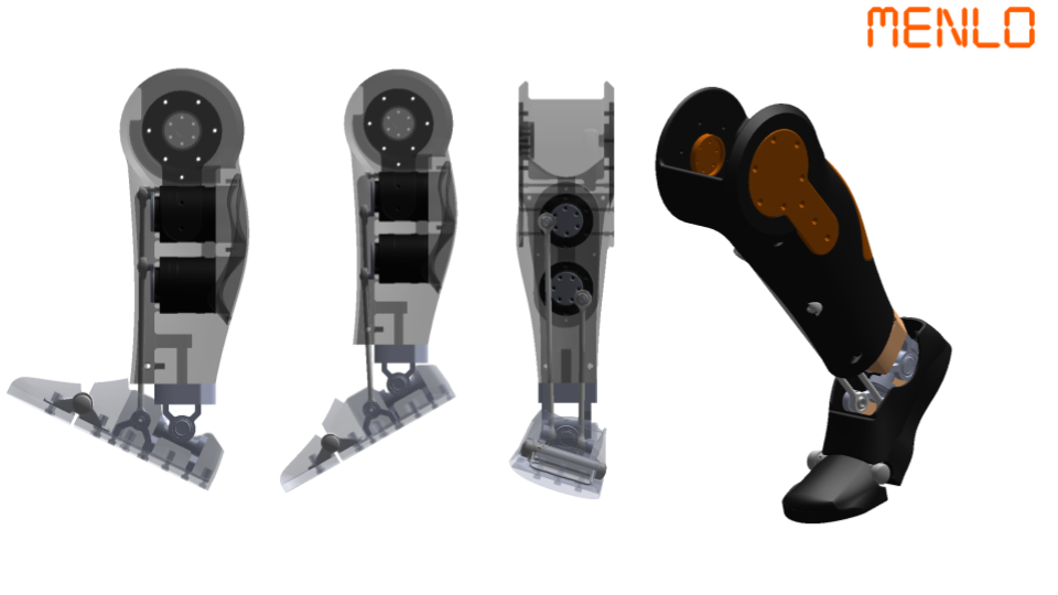 Figure: Passive toe joint design
Similar to how human toes passively bend to conform to the ground during stance, an articulated toe increases effective contact area and helps distribute load more evenly. The main benefit appears during the stance-to-push-off transition.
As the body moves forward, the toe rocker allows the foot to roll rather than pivot on a rigid edge. This reduces peak local forces, maintains ground contact, and increases effective contact area, improving traction stability and forward propulsion.
In Asimov, this is implemented as an additional toe hinge that is articulated but not actively actuated. The toe joint is passive and compliant, using elastic/spring-like return behavior instead of a dedicated motor drive. This approach captures most toe-rollover benefits while avoiding the added complexity, mass, and control burden of another powered joint.
The passive toe joint stiffness is 2.67 Nm. The toe motion ranges are:
- Left toe:
-1.05 ~ 0.00 rad - Right toe:
0.00 ~ 1.05 rad
4. References
- Unitree G1 developer documentation (parallel-ankle context): https://support.unitree.com/home/en/G1_developer/basic_motion_routine
After the previous chapters, you should now have a clear understanding of our mechanical design. You can now begin manufacturing the parts to build your robot in 3D Printing and Fabrication.
How is this guide?