Frame and Structural Components
This chapter describes how the Asimov 1 humanoid frame is organized, how major structural modules connect, and why the structural design choices were made.
CAD Files
Download STEP file here
You can refer to the mechanical STEP files on GitHub.
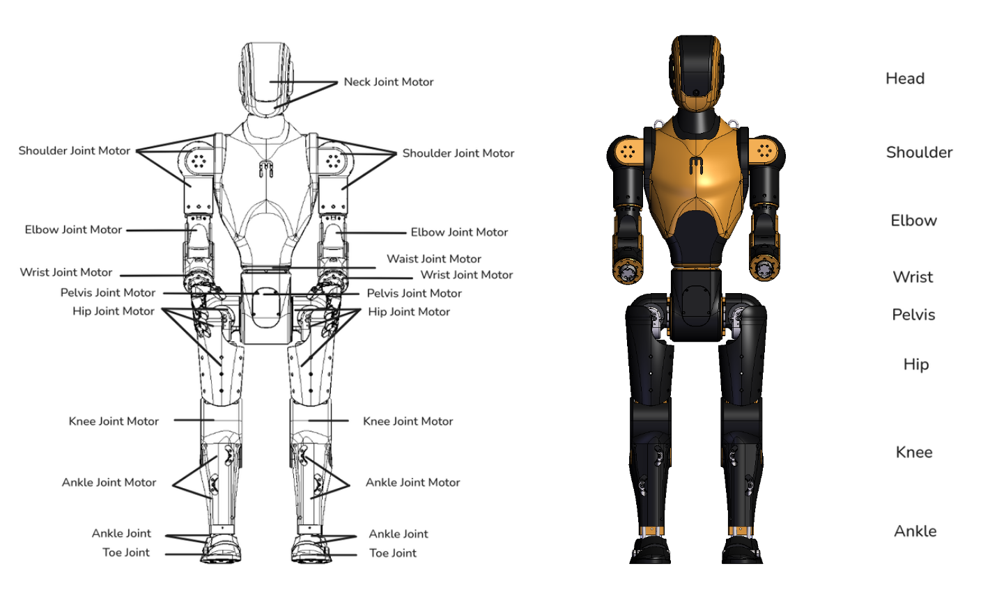
1. Asimov Humanoid Structural Architecture
The Asimov 1 humanoid is organized into two main sections: the upper body and the lower body. The upper body consists of the head, shoulders, elbows and torso. The lower body consists of the pelvis, legs and toes. The robot has 25 active degrees of freedom, with 2 additional passive toe joints. This structure defines the main load-bearing frame of the robot and the primary mechanical interfaces between major assemblies.
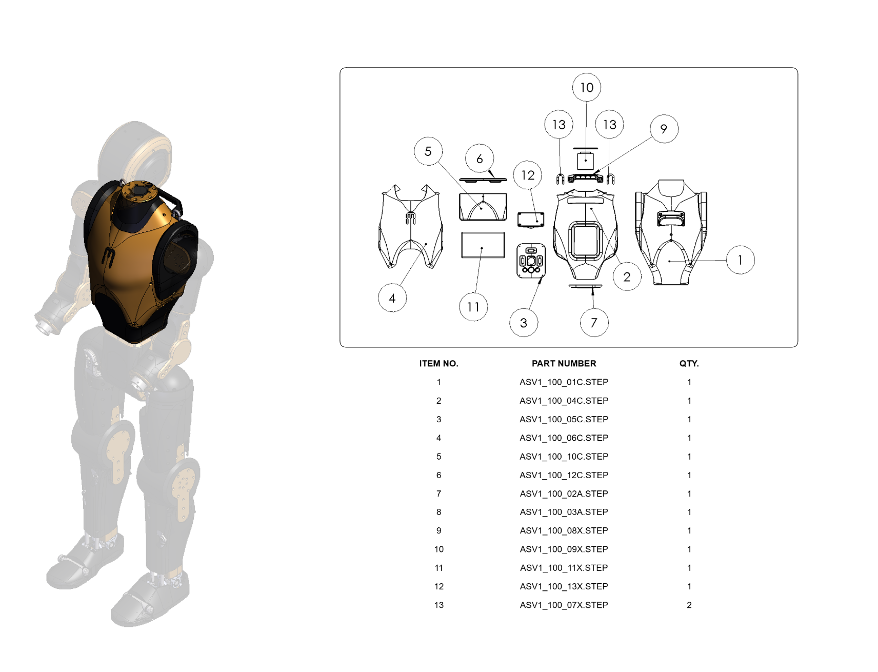
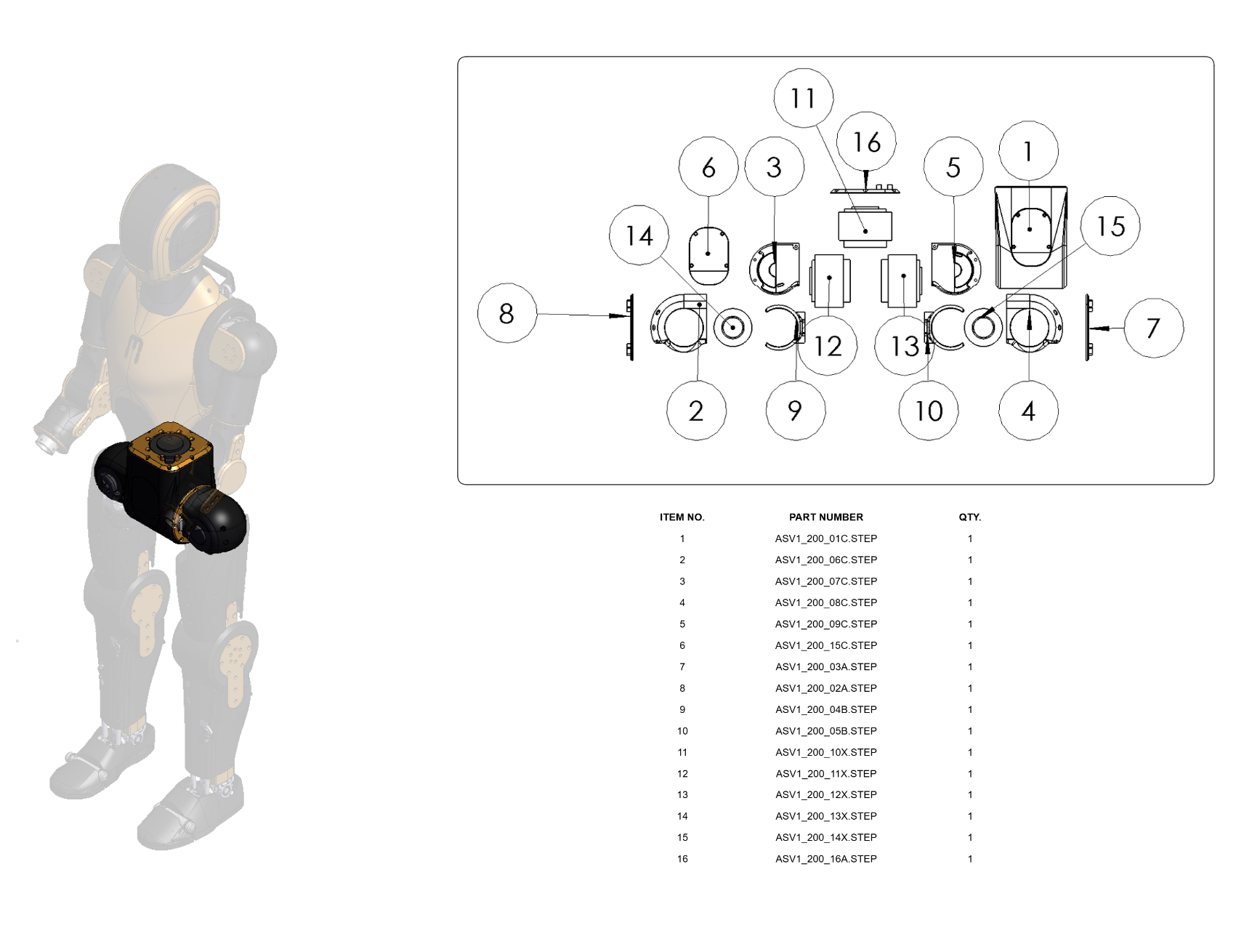
2. Structural Breakdown of Main Modules
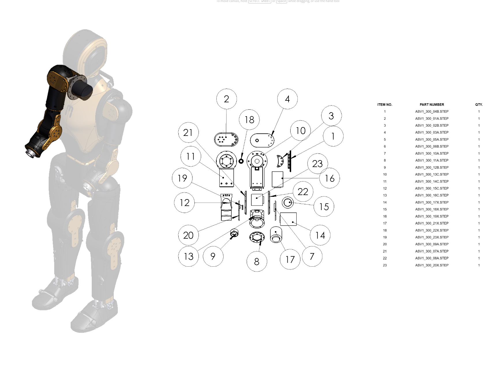
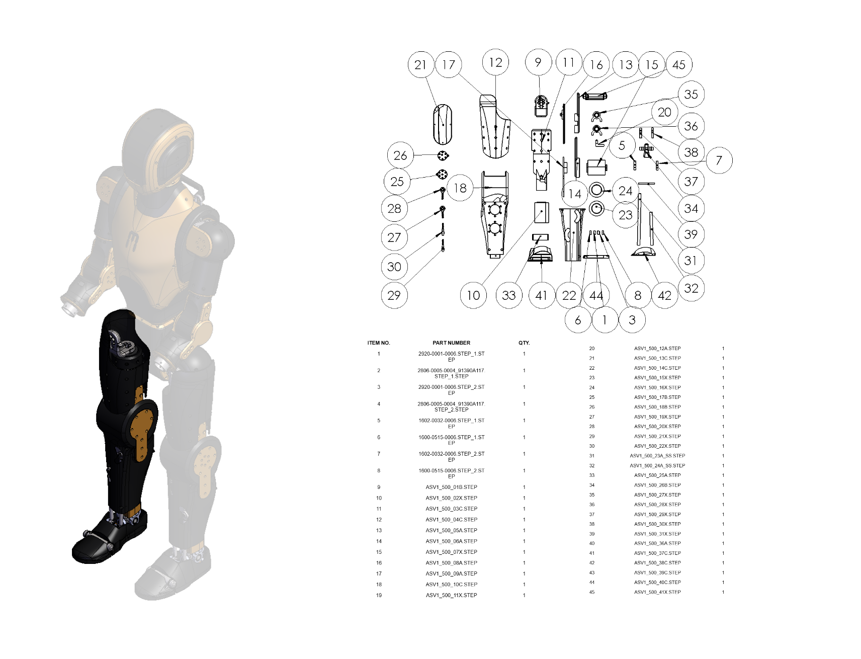
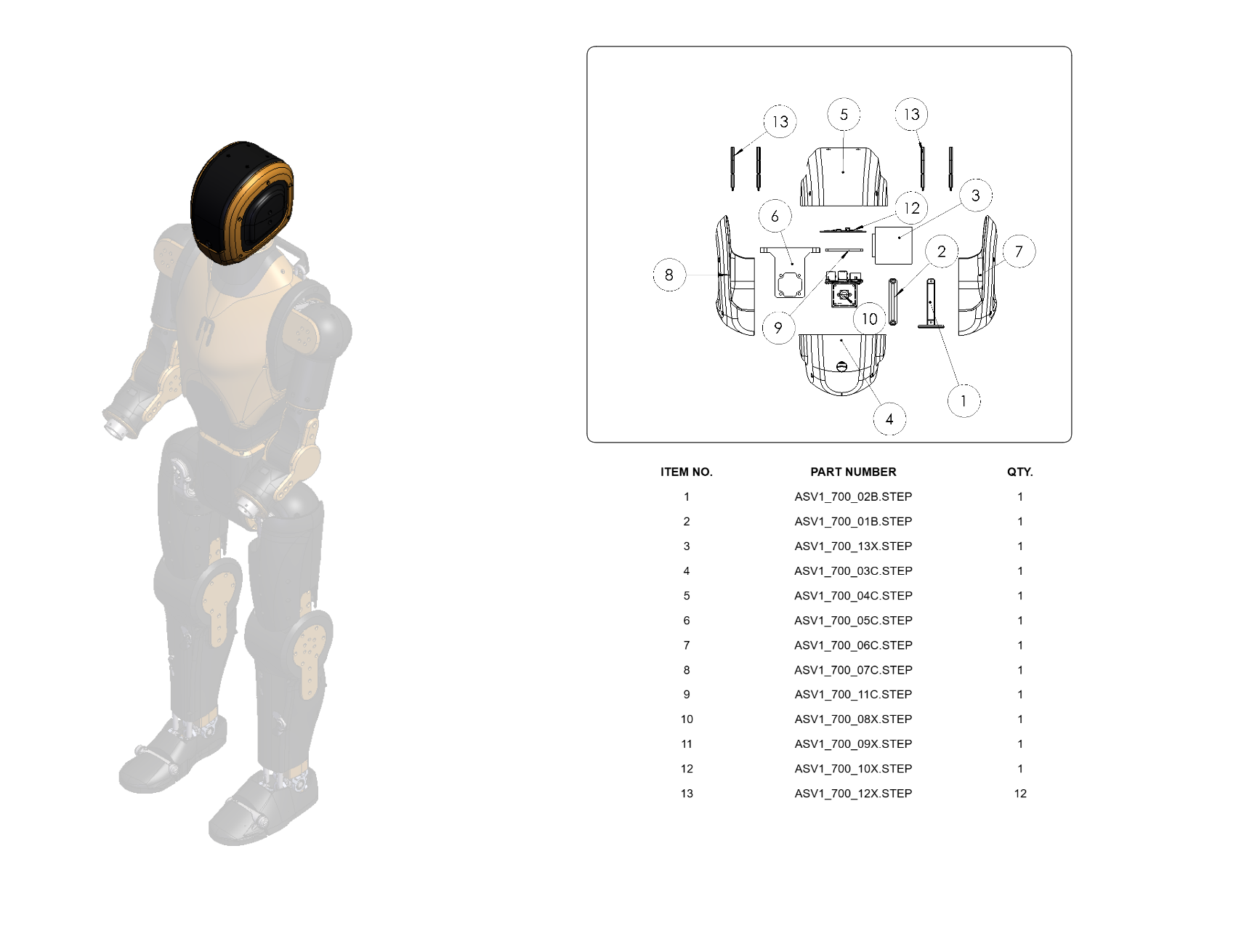
This exploded view shows the structural parts included in the CAD files for manufacturing. Components are labeled with indices so you can use this diagram as a checklist to confirm that all CAD-modeled parts are present. Fasteners and other standard hardware, such as screws, nuts, and washers, are not included.
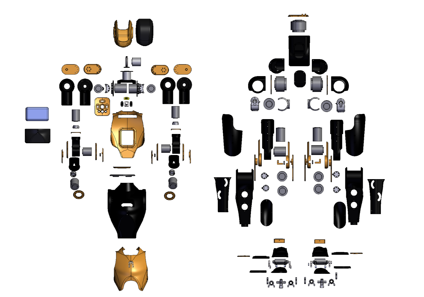 Figure: Exploded view of Asimov 1 part. Left: upper body, Right: Lower body
Torso Module
Pelvis Module
Arm Module (Left)
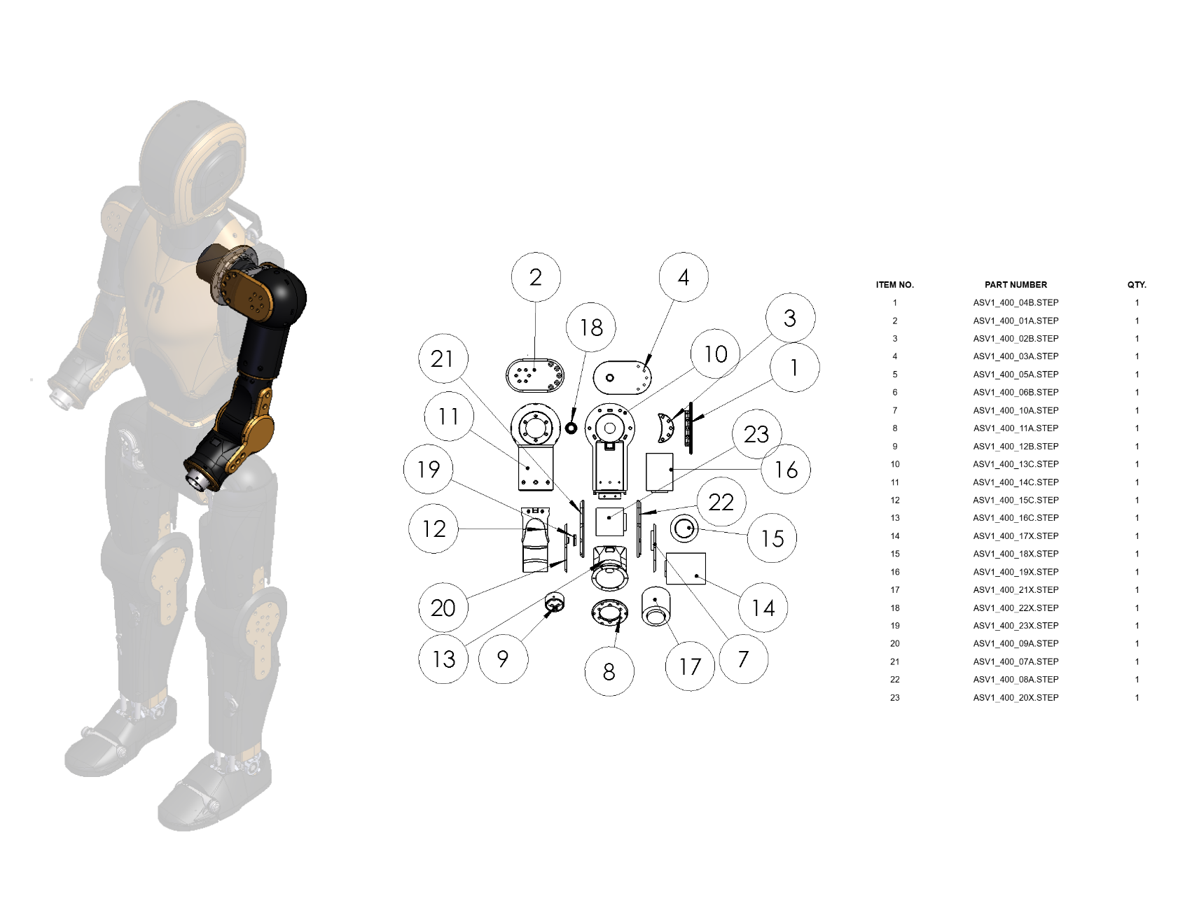
Arm Module (Right)
Leg Module (Left)
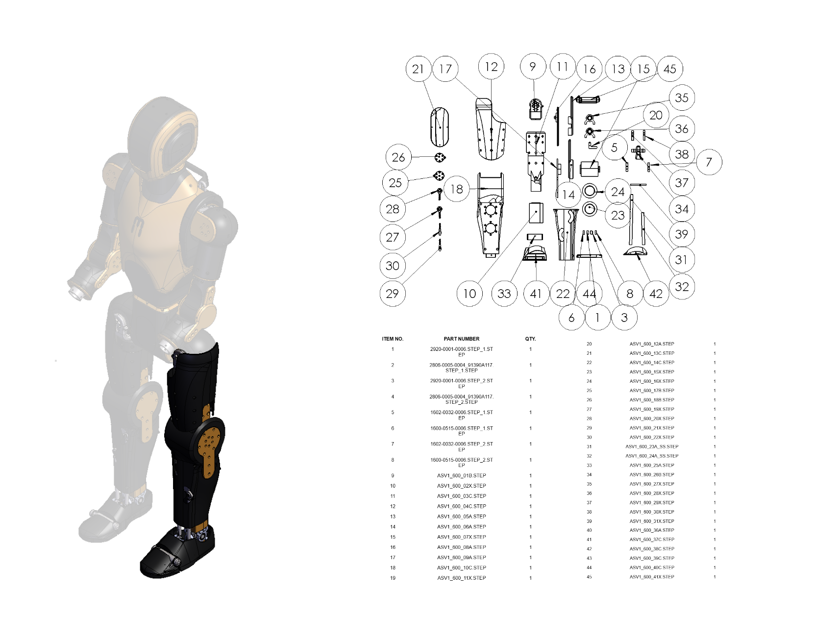
Leg Module (Right)
Head Module
3. Joint Structural Packaging
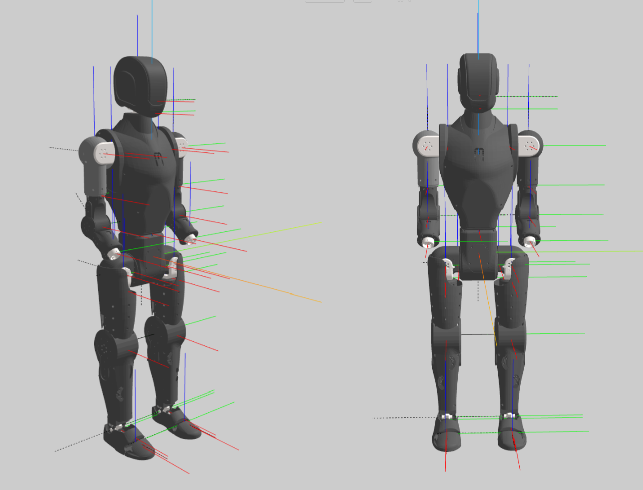
Joint Coordinate
The picture below shows the joint rotation axis with 0 joint position. The frame convention is blue for z, red for x, and green for y.
Joint Index and Joint rotation range
| Joint Index | Joint Name | Motion Range (rad) | Axis (xyz) |
|---|---|---|---|
| 1 | left_hip_pitch_joint | -2.09 ~ 1.00 | 0 1 0 |
| 2 | left_hip_roll_joint | -0.79 ~ 0.79 | 1 0 0 |
| 3 | left_hip_yaw_joint | -0.79 ~ 0.79 | 0 0 -1 |
| 4 | left_knee_joint | 0.00 ~ 1.50 | 0 1 0 |
| 5 | left_ankle_pitch_joint | -0.35 ~ 0.35 | 0 1 0 |
| 6 | left_ankle_roll_joint | -0.10 ~ 0.10 | -1 0 0 |
| 7 | left_toe_joint | -1.05 ~ 0.00 | 0.010532 0.99994 0 |
| 8 | right_hip_pitch_joint | -1.00 ~ 2.09 | 0 -1 0 |
| 9 | right_hip_roll_joint | -0.79 ~ 0.79 | 1 0 0 |
| 10 | right_hip_yaw_joint | -0.79 ~ 0.79 | 0 0 -1 |
| 11 | right_knee_joint | -1.50 ~ 0.00 | 0 -1 0 |
| 12 | right_ankle_pitch_joint | -0.35 ~ 0.35 | 0 -1 0 |
| 13 | right_ankle_roll_joint | -0.10 ~ 0.10 | -1 0 0 |
| 14 | right_toe_joint | 0.00 ~ 1.05 | 0.0074685 -0.99997 0 |
| 15 | waist_yaw_joint | -1.57 ~ 1.57 | 0 0 1 |
| 16 | neck_yaw_joint | -1.57 ~ 1.57 | 0 0 1 |
| 17 | neck_pitch_joint | -0.79 ~ 0.79 | 0 1 0 |
| 18 | left_shoulder_pitch_joint | -3.14 ~ 0.87 | 0 1 0 |
| 19 | left_shoulder_roll_joint | -1.57 ~ 0.00 | -1 0 0 |
| 20 | left_shoulder_yaw_joint | -1.57 ~ 1.57 | 0 0 -1 |
| 21 | left_elbow_joint | 0.00 ~ 2.44 | 0 -1 0 |
| 22 | left_wrist_yaw_joint | -3.14 ~ 3.14 | 0.766 0 -0.64 |
| 23 | right_shoulder_pitch_joint | -0.87 ~ 3.14 | 0 -1 0 |
| 24 | right_shoulder_roll_joint | 0.00 ~ 1.57 | -1 0 0 |
| 25 | right_shoulder_yaw_joint | -1.57 ~ 1.57 | 0 0 -1 |
| 26 | right_elbow_joint | -2.44 ~ 0.00 | 0 1 0 |
| 27 | right_wrist_yaw_joint | -3.14 ~ 3.14 | 0.766 0 -0.64 |
If you want to know more details about the joints, welcome to the next chapter Joint Design and Actuation, where we covered the actuators, ankle and toe joints design.
How is this guide?