Assembly Steps
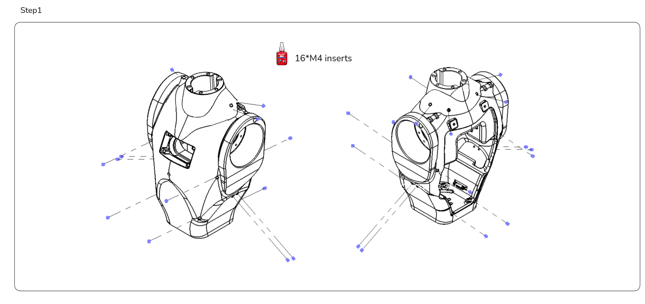
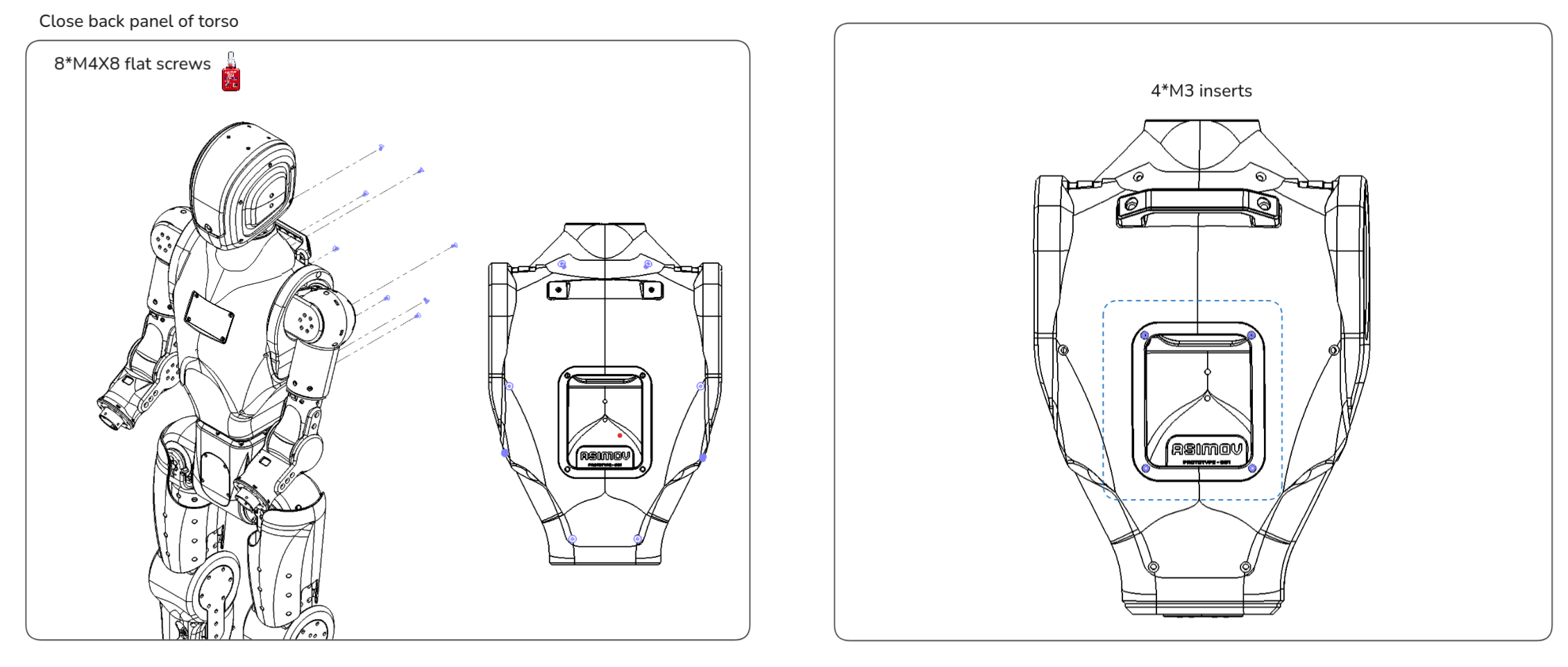
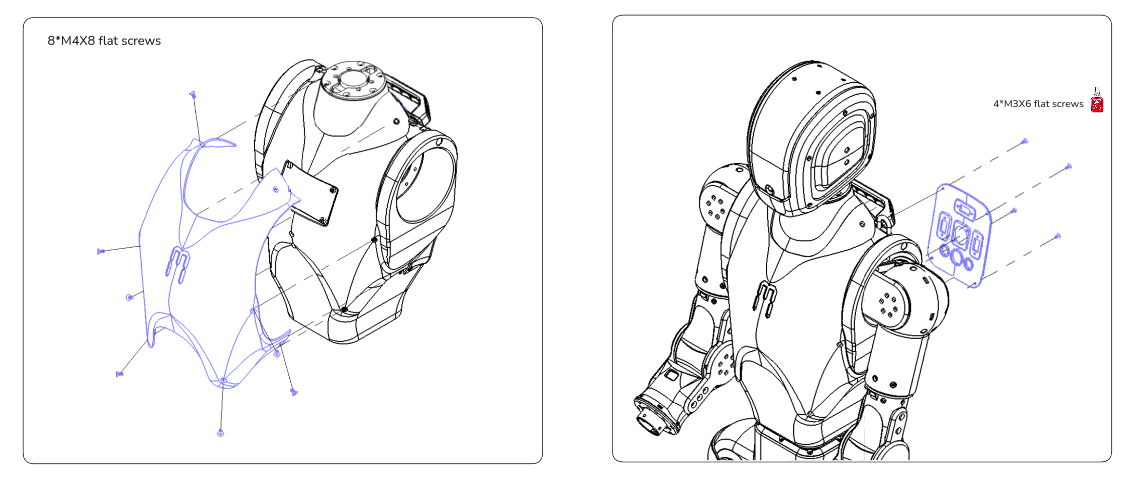
1. Torso module 🧍
Mechanical parts list
| Part Number | Qty | Notes |
|---|---|---|
| ASV1_100_01C | 1 | MJF PA 12, Dyeing-Dyed Black |
| ASV1_100_02A | 1 | Aluminum 7075, Bead Blasting + Anodizing (Brass) |
| ASV1_100_03A | 1 | Aluminum 7075, Bead Blasting + Anodizing (Brass) |
| ASV1_100_04C | 1 | MJF PA 12, Glossy Spray Paint (Brass) |
| ASV1_100_05C | 1 | MJF PA 12, Glossy Spray Paint (Brass) |
| ASV1_100_06C | 1 | MJF PA 12, Glossy Spray Paint (Brass) |
| ASV1_100_10C | 1 | MJF PA 12, Dyeing-Dyed Black |
| ASV1_100_12C | 1 | MJF PA 12, Dyeing-Dyed Black |
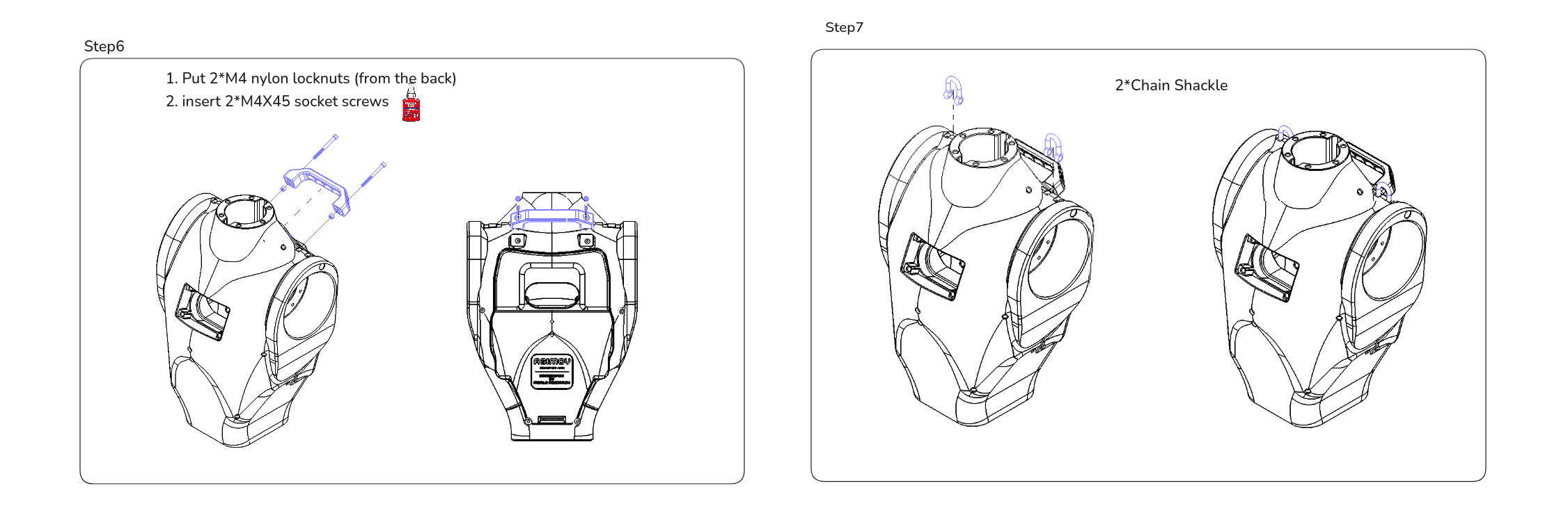
| ASV1_100_07X | 2 | Chain Shackle, 4031N11, McMaster |
| ASV1_100_08X | 1 | Pull Handle, 5193A1, McMaster |
Electronics list
| Part Number | Qty | Notes |
|---|---|---|
| ASV1_100_09X | 1 | ENCOS Motor, EC-A4310-P2-36, used for neck_yaw_joint (Motor ID 24) |
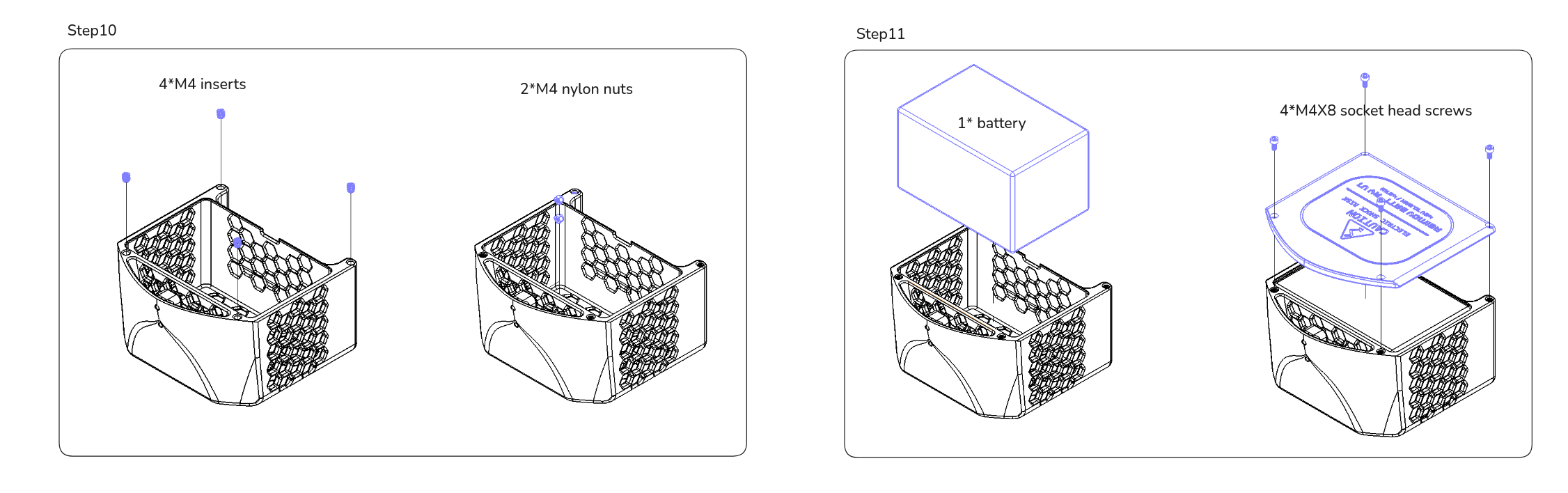
| ASV1_100_11X | 1 | Li-ion L150xW85xD95 mm (10.5Ah at 46.8v), 13S4P, Shenzhen Kang Li Electronic Technology Co., Ltd. |
| ASV1_100_13X | 1 | Speaker, 4 Ohm 10 W, 433-1229-ND, DigiKey |
| Motion Control Board | 1 | motion control board of Asimov |
Fasteners list
| Item | Qty |
|---|---|
| M3 x 6 flat head screws | 4 |
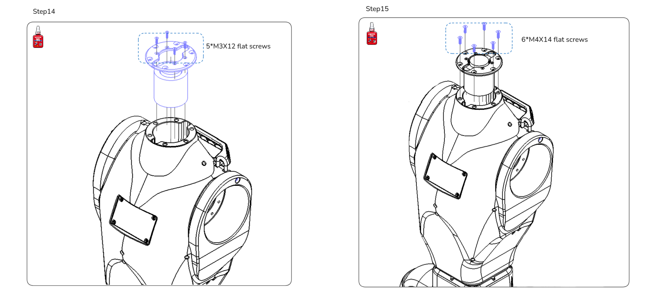
| M3 x 12 flat head screws | 5 |
| M4 x 8 flat head screws | 16 |
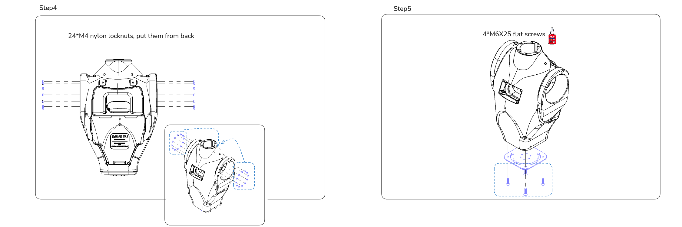
| M6 x 25 flat head screws | 4 |
| M4 x 14 flat head screws | 6 |
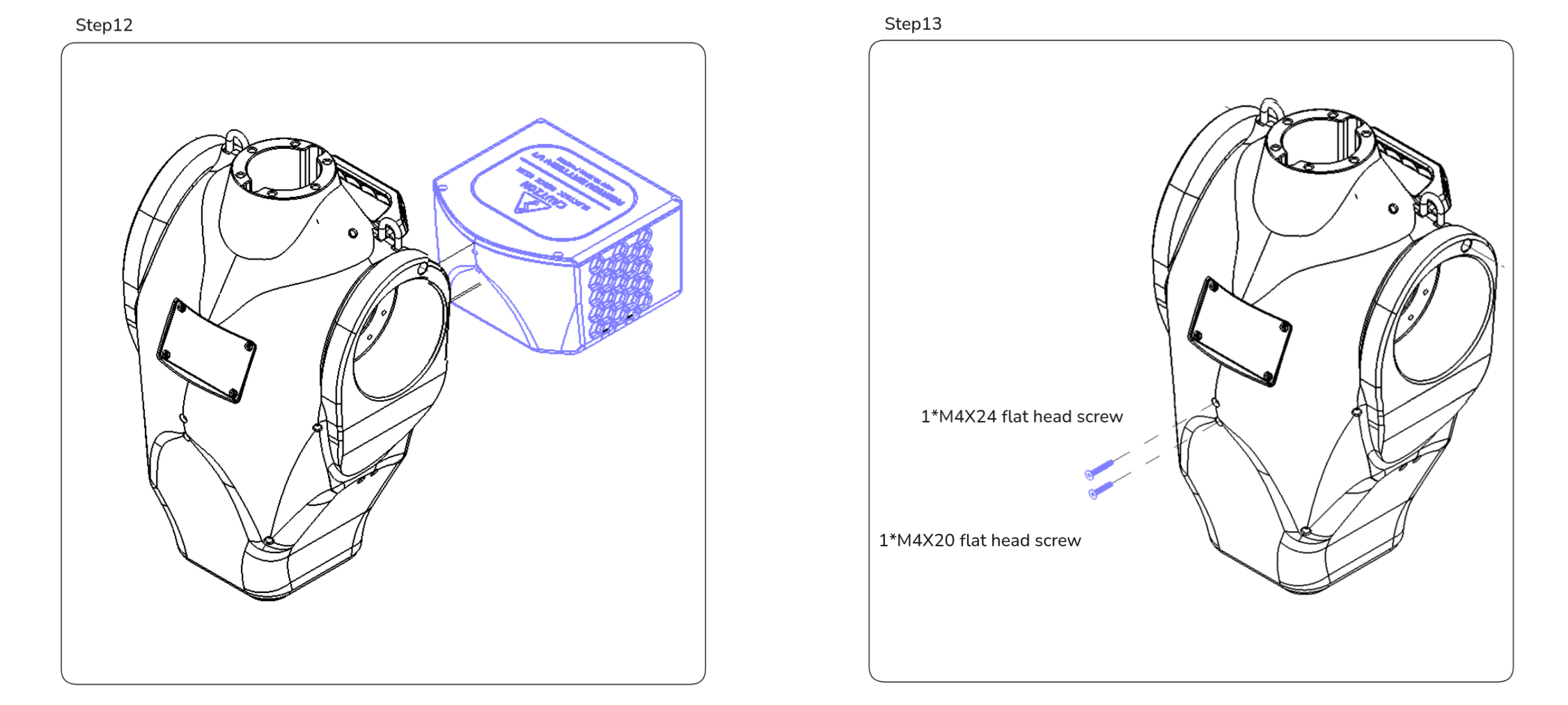
| M4 x 20 flat head screws | 1 |
| M4 x 24 flat head screws | 1 |
| M4 x 8 socket head screws | 4 |
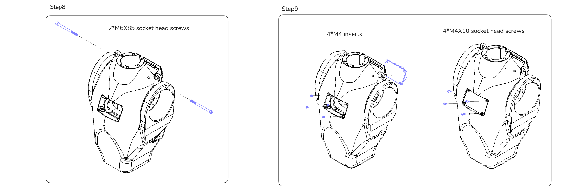
| M4 x 10 socket head screws | 4 |
| M4 x 20 socket head screws | 6 |
| M4 x 30 socket head screws | 24 |
| M4 x 45 socket head screws | 2 |
| M6 x 85 socket head screws | 2 |
| M3 inserts | 4 |
| M4 inserts | 24 |
| M4 nylon locknuts | 28 |
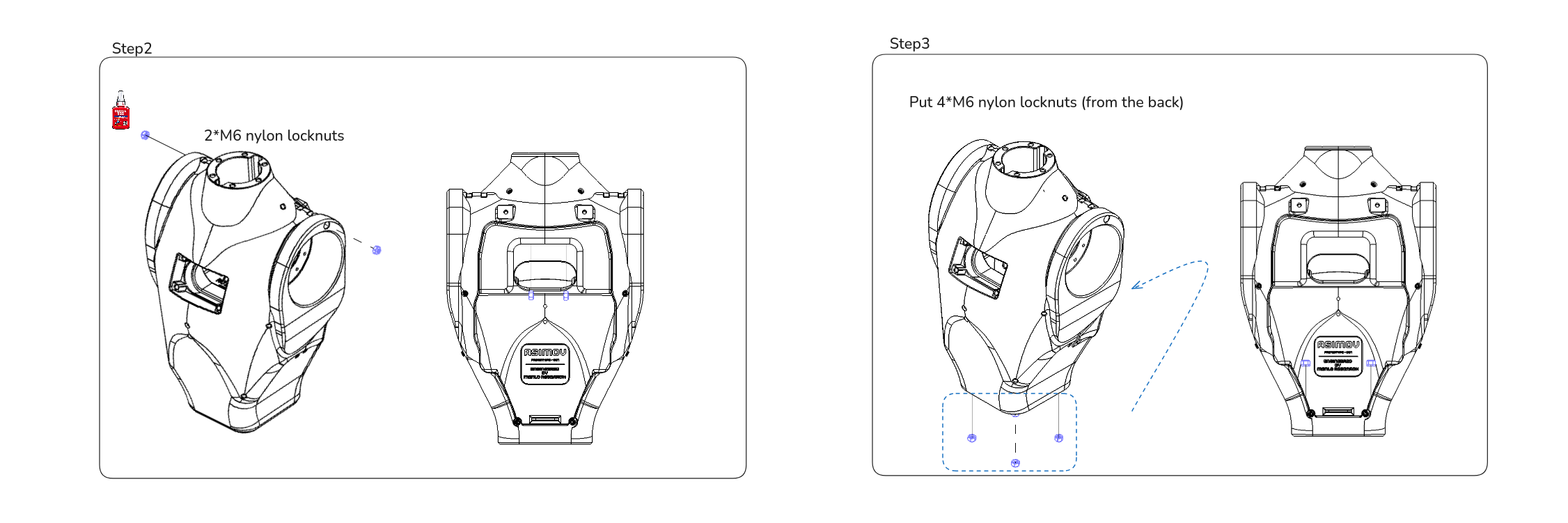
| M6 nylon locknuts | 6 |
| Loctite 222 thread locker | As needed |
Assembly Steps
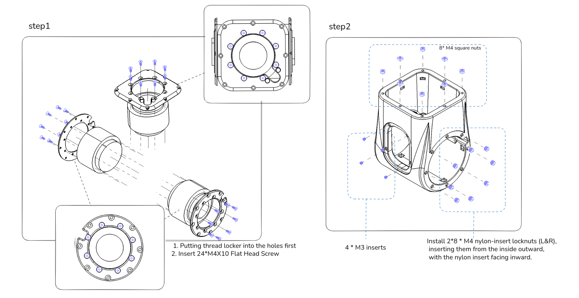
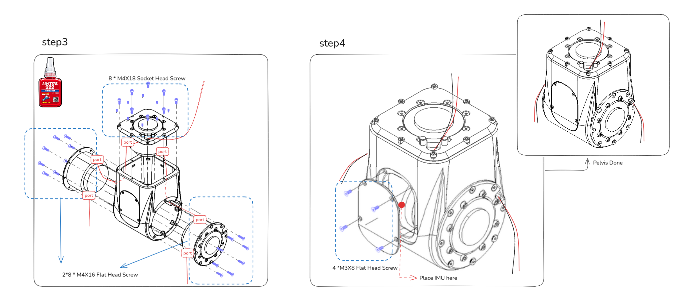
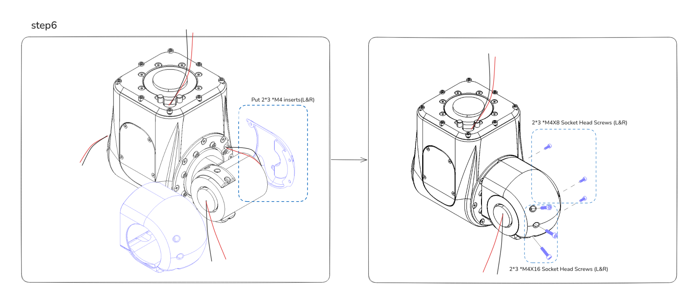
2. Pelvis module 🤖
Mechanical parts list
| Part Number | Qty | Notes |
|---|---|---|
| ASV1_200_01C | 1 | MJF PA 12, Dyeing-Dyed Black |
| ASV1_200_02A | 1 | Aluminum 7075, Bead Blasting + Anodizing (Brass) |
| ASV1_200_03A | 1 | Aluminum 7075, Bead Blasting + Anodizing (Brass) |
| ASV1_200_04B | 1 | SLM 316L, As Printed |
| ASV1_200_05B | 1 | SLM 316L, As Printed |
| ASV1_200_06C | 1 | MJF PA 12, Dyeing-Dyed Black |
| ASV1_200_07C | 1 | MJF PA 12, Dyeing-Dyed Black |
| ASV1_200_08C | 1 | MJF PA 12, Dyeing-Dyed Black |
| ASV1_200_09C | 1 | MJF PA 12, Dyeing-Dyed Black |
| ASV1_200_15C | 1 | MJF PA 12, Dyeing-Dyed Black |
| ASV1_200_16A | 1 | Aluminum 7075, Bead Blasting + Anodizing (Brass) |
Electronics list
| Part Number | Qty | Notes |
|---|---|---|
| ASV1_200_10X | 1 | ENCOS Motor, EC-A6416-P2-25, used for left_hip_pitch_joint (Motor ID 1) |
| ASV1_200_11X | 1 | ENCOS Motor, EC-A6416-P2-25, used for right_hip_pitch_joint (Motor ID 7) |
| ASV1_200_12X | 1 | ENCOS Motor, EC-A6416-P2-25, used for waist_yaw_joint (Motor ID 23) |
| ASV1_200_13X | 1 | ENCOS Motor, EC-A5013-H17-100, used for left_hip_roll_joint (Motor ID 2) |
| ASV1_200_14X | 1 | ENCOS Motor, EC-A5013-H17-100, used for right_hip_roll_joint (Motor ID 8) |
| IMU | 1 | 6-axis IMU |
Fasteners list
| Item | Qty |
|---|---|
| M3 x 8 flat head screws | 4 |
| M4 x 10 flat head screws | 24 |
| M4 x 16 flat head screws | 16 |
| M4 x 6 socket head screws | 12 |
| M4 x 8 socket head screws | 6 |
| M4 x 12 socket head screws | 12 |
| M4 x 16 socket head screws | 6 |
| M4 x 18 socket head screws | 8 |
| M3 inserts | 4 |
| M4 inserts | 6 |
| M4 nylon-insert locknuts | 16 |
| M4 square nuts | 8 |
| Loctite 222 thread locker | As needed |
Assembly Steps
Step 3-2: Plug the three pre-cut XT30(2+2) cable branches into the Left Hip Pitch, Right Hip Pitch, and Waist Yaw motor ports. Route the cables out through the designated gaps in the cover, leaving the ends accessible for later connection.
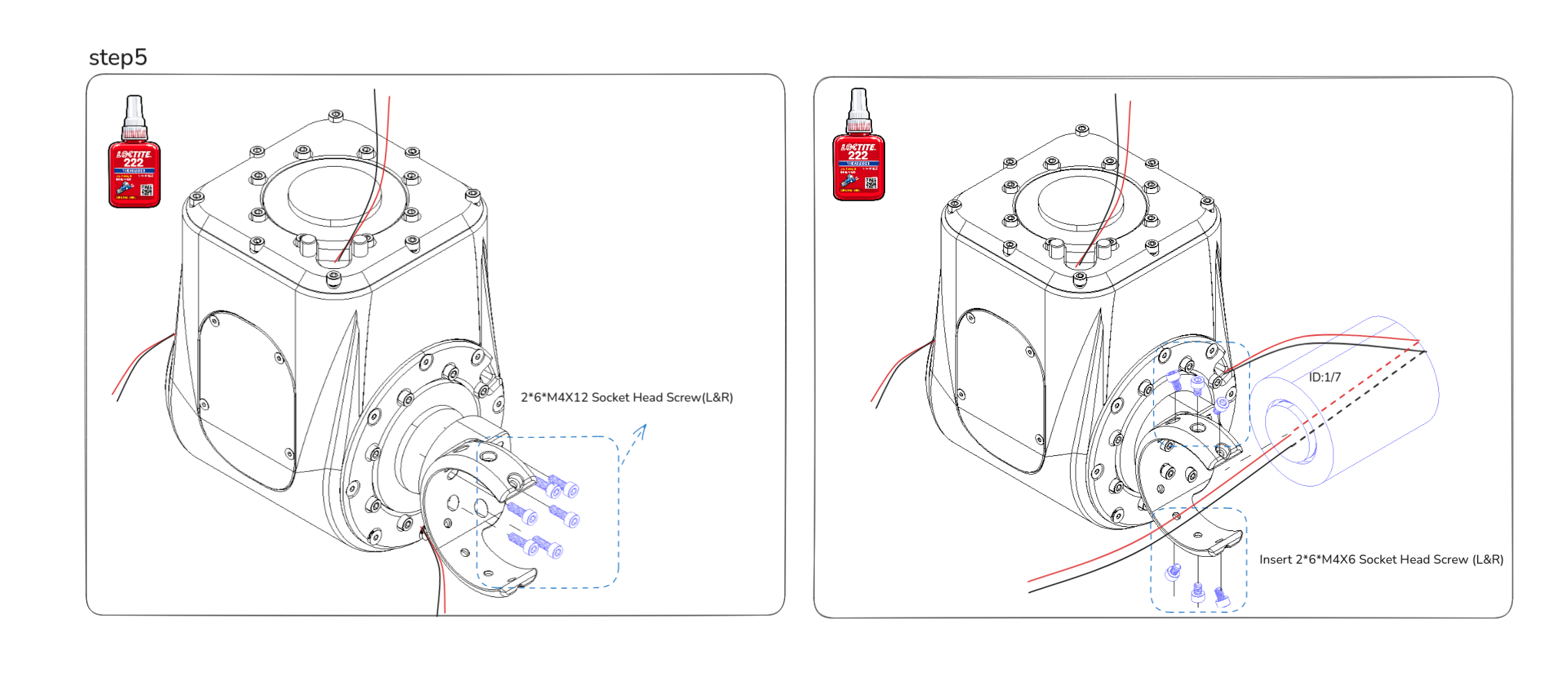 Step 5-2: Hip Pitch to Hip Roll motor wiring: Connect the pre-cut XT30(2+2) cable from the Left Hip Pitch motor to the back port of the Left Hip Roll motor. After plugging it into the back port, route the cable through the Hip Roll motor shaft and guide it out from the motor. Repeat the same process for the right leg.
3. Arms module 🦾
This section shows the left arm assembly. The right arm is assembled the same way as a mirrored build, using the corresponding 300 mirrored part IDs.
The fastener tables and steps here cover the left arm only.
Mechanical parts list
| Part Number | Qty | Notes |
|---|---|---|
| ASV1_400_02B | 1 | SLM 316L, As Printed |
| ASV1_400_03B | 1 | SLM 316L, As Printed |
| ASV1_400_04A | 1 | Aluminum 7075, Bead Blasting + Anodizing (Brass) |
| ASV1_400_05A | 1 | Aluminum 7075, Bead Blasting + Anodizing (Brass) |
| ASV1_400_06C | 1 | MJF PA 12, Dyeing-Dyed Black |
| ASV1_400_07C | 1 | MJF PA 12, Dyeing-Dyed Black |
| ASV1_400_11A | 1 | Aluminum 7075, Bead Blasting + Anodizing (Brass) |
| ASV1_400_12B | 1 | SLM 316L, As Printed |
| ASV1_400_13A | 1 | Aluminum 7075, Bead Blasting + Anodizing (Brass) |
| ASV1_400_14A | 1 | Aluminum 7075, Bead Blasting + Anodizing (Brass) |
| ASV1_400_15C | 1 | MJF PA 12, Dyeing-Dyed Black |
| ASV1_400_16C | 1 | MJF PA 12, Dyeing-Dyed Black |
| ASV1_400_17A | 1 | Aluminum 7075, Bead Blasting + Anodizing (Brass) |
| ASV1_400_18A | 1 | Aluminum 7075, Bead Blasting + Anodizing (Brass) |
| ASV1_400_19A | 1 | Aluminum 7075, Bead Blasting + Anodizing (Brass) |
| ASV1_400_20B | 1 | SLM 316L, As Printed |
| ASV1_400_10X | 1 | Flanged Ball Bearing, 4390N159, McMaster |
| ASV1_400_21X | 1 | Flanged Ball Bearing, 4390N159, McMaster |
Electronics list
| Part Number | Qty | Notes |
|---|---|---|
| ASV1_400_01X | 1 | ENCOS Motor, EC-A5013-H17-100, used for left_shoulder_pitch_joint (Motor ID 13) |
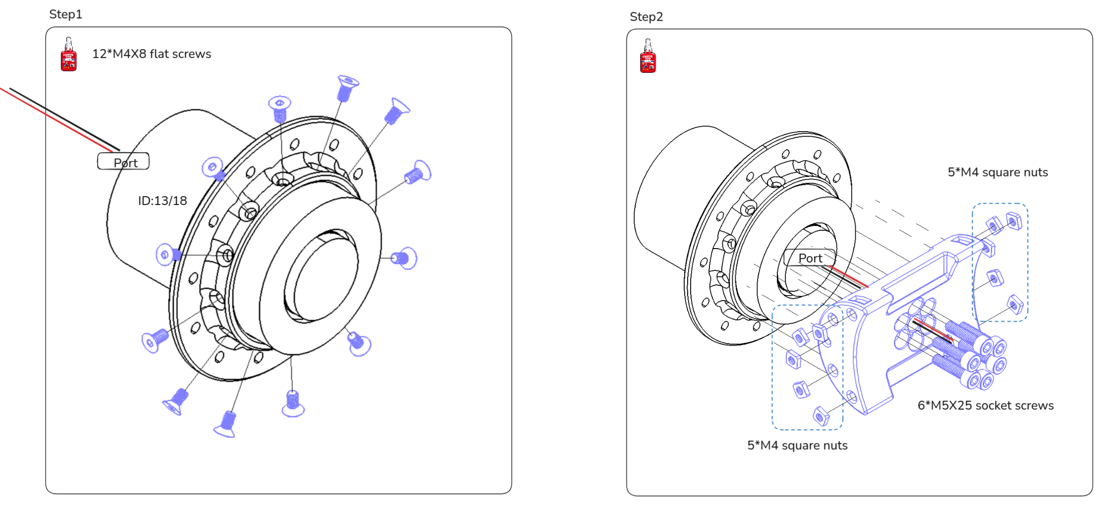
| ASV1_400_08X | 1 | ENCOS Motor, EC-A4315-P2-36, used for left_shoulder_roll_joint (Motor ID 14) |
| ASV1_400_09X | 1 | ENCOS Motor, EC-A3814-H14-107, used for left_shoulder_yaw_joint (Motor ID 15) |
| ASV1_400_22X | 1 | ENCOS Motor, EC-A4310-P2-36, used for left_elbow_joint (Motor ID 16) |
| ASV1_400_23X | 1 | ENCOS Motor, EC-A4310-P2-36, used for left_wrist_yaw_joint (Motor ID 17) |
Fasteners list
| Item | Qty |
|---|---|
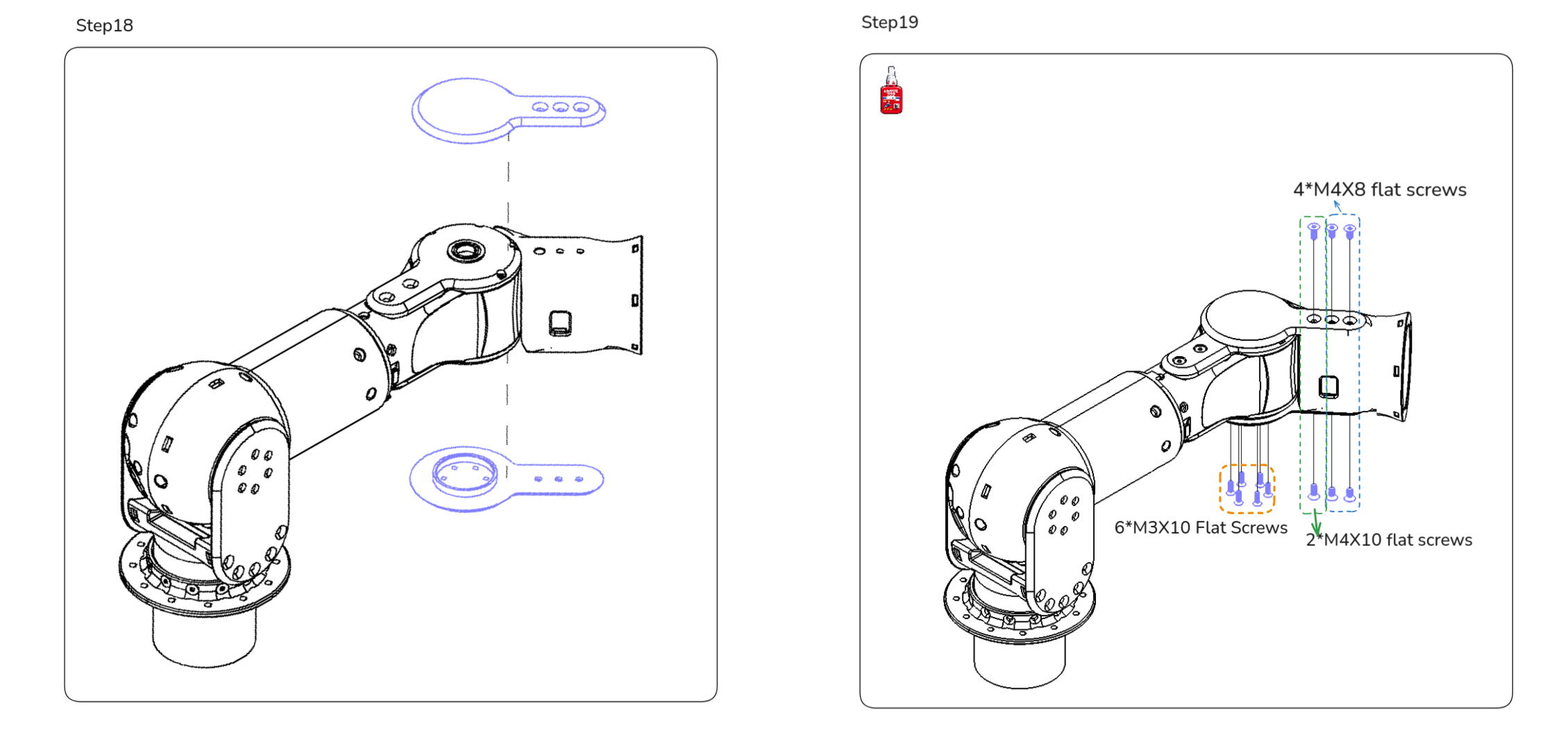
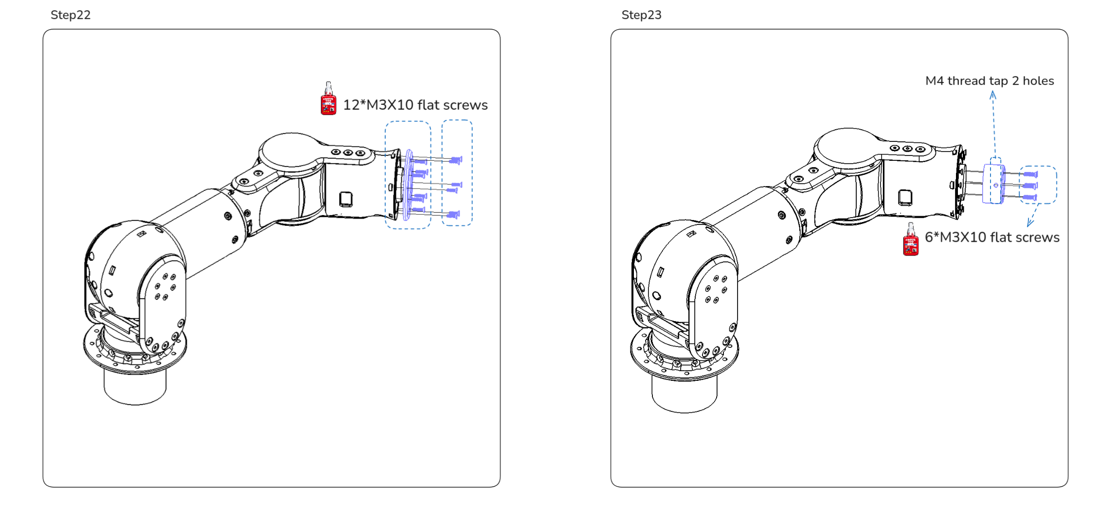
| M3 x 10 flat head screws | 30 |
| M3 x 12 flat head screws | 14 |
| M3 x 16 flat head screws | 6 |
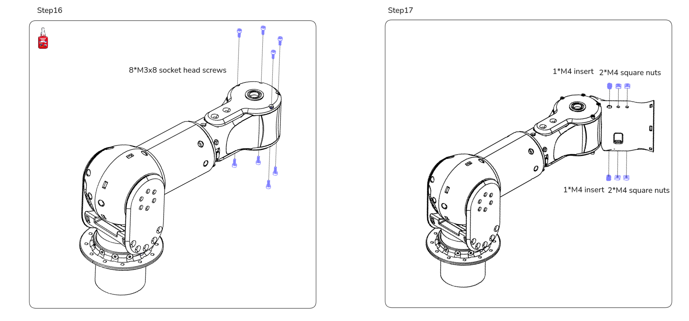
| M3 x 8 socket head screws | 8 |
| M4 x 8 flat head screws | 20 |
| M4 x 12 flat head screws | 10 |
| M4 x 8 socket head screws | 15 |
| M4 x 16 socket head screws | 6 |
| M4 x 20 socket head screws | 6 |
| M4 x 25 socket head screws | 4 |
| M5 x 25 socket head screws | 6 |
| M3 inserts | 8 |
| M4 inserts | 6 |
| M3 square nuts | 6 |
| M4 square nuts | 24 |
| M4 thread tap | 1 |
| Loctite 222 thread locker | As needed |
Assembly Steps
Step 2-2: Route the shoulder pitch motor cable with the XT30(2+2) connector through the motor’s hollow shaft.
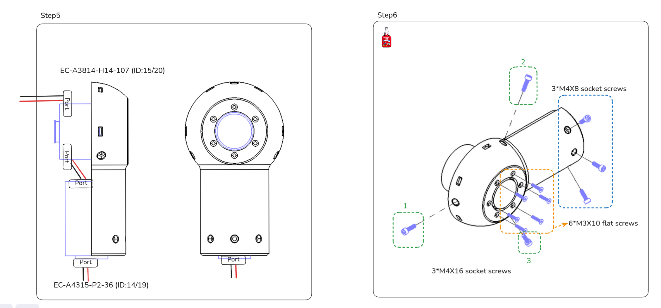
Step 5-2 Shoulder Roll to Shoulder Yaw motor wiring: Connect the pre-cut XT30(2+2) cable from the Shoulder Roll motor to the top port of the Shoulder Yaw motor.
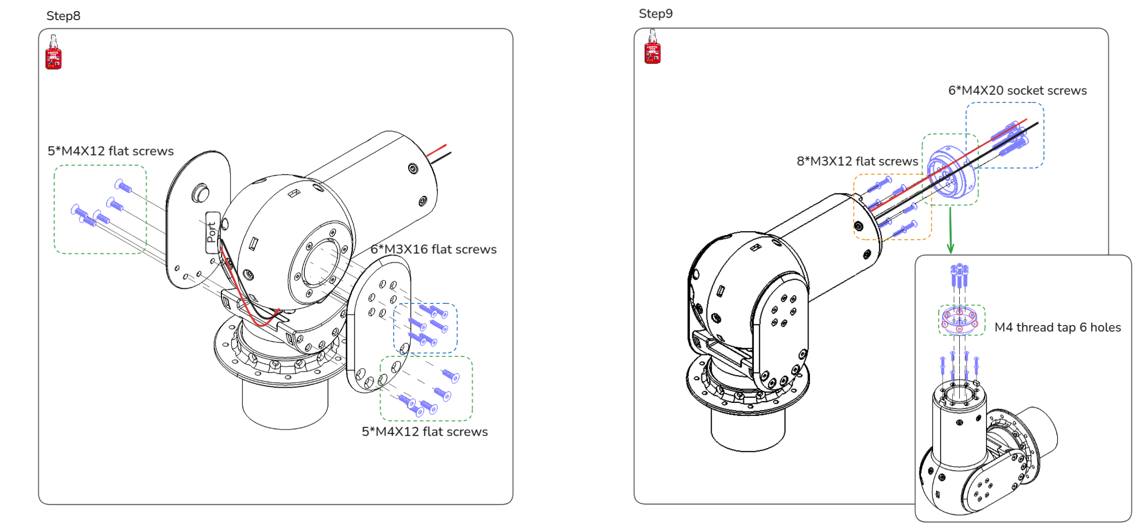
Step 8-2 Shoulder Pitch to Shoulder Roll motor wiring: Route the XT30(2+2) cable from the Shoulder Pitch motor through the hollow shaft, then attach it to the Shoulder Roll motor side port. Repeat for both arms.
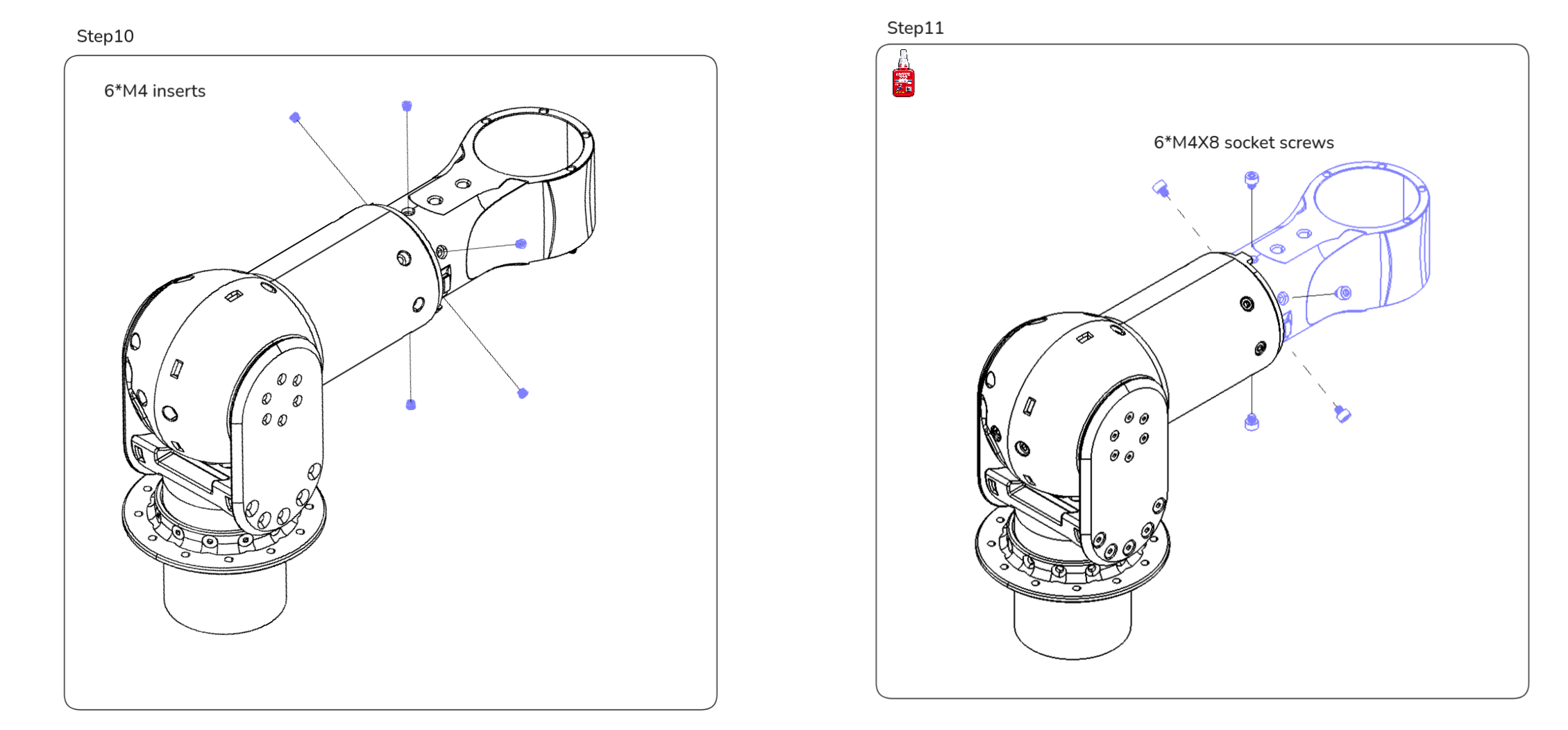
Step 11-2 Shoulder Yaw to Elbow motor wiring: Connect the pre-cut XT30(2+2) cable from the Shoulder Yaw motor to the side port of the Elbow motor.
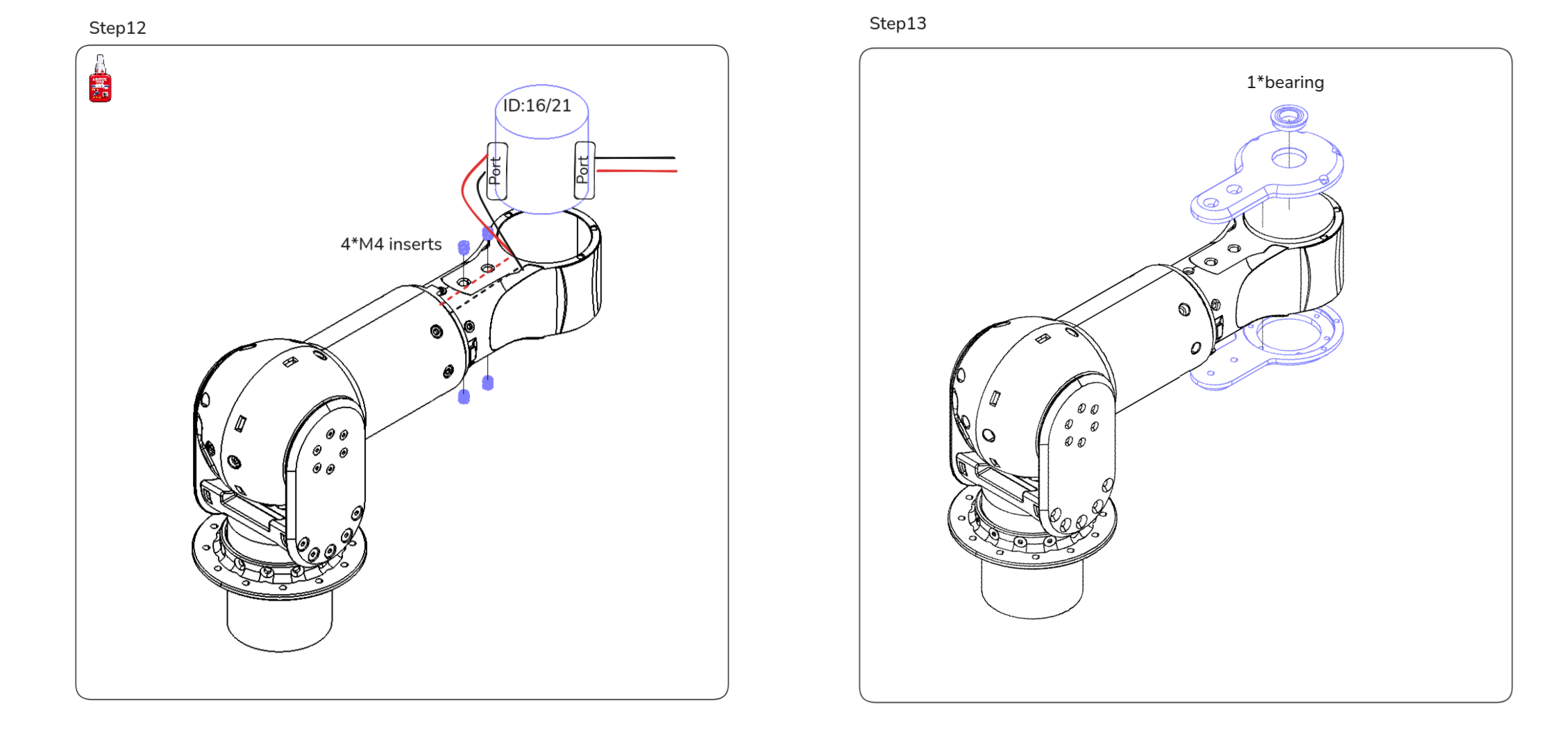
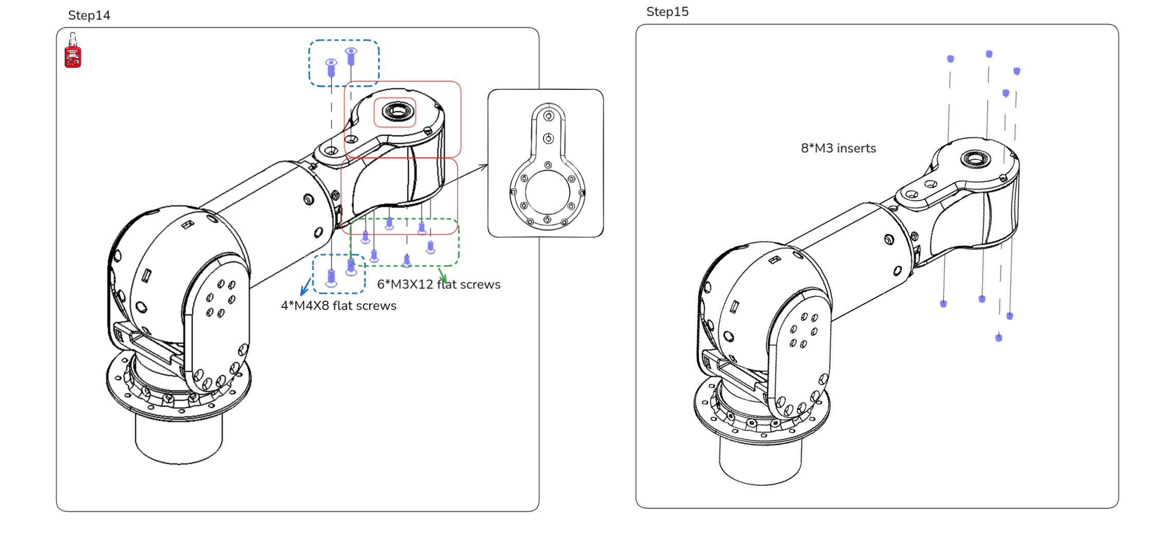
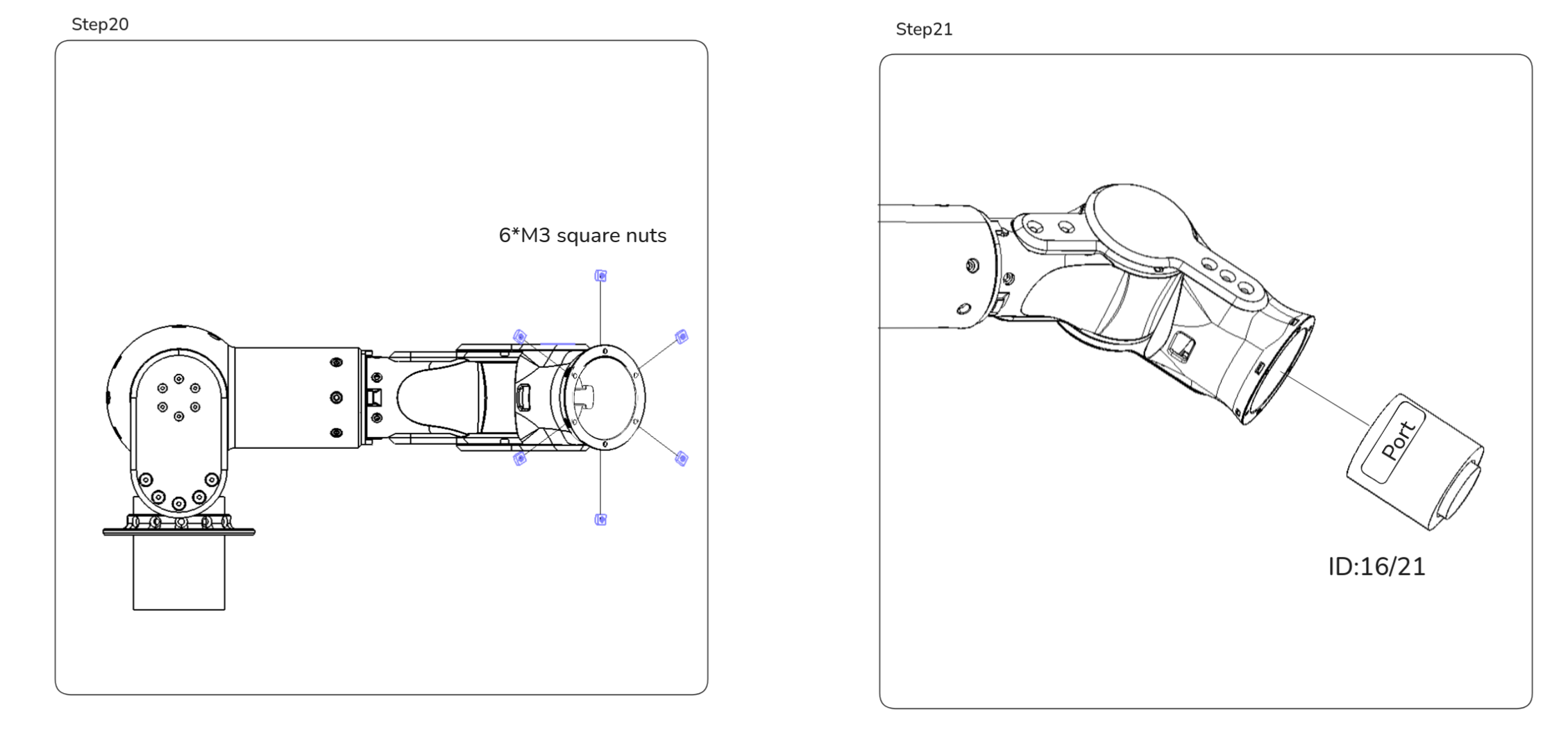
Step 16-2 Elbow to Wrist Yaw motor wiring: Connect the pre-cut XT30(2+2) cable from the Elbow motor to the side port of the Wrist Yaw motor.
4. Legs module 🦿
This section shows the left leg assembly. The right leg is assembled the same way as a mirrored build, using the corresponding 500 mirrored part IDs.
The fastener tables and steps here cover the left leg only.
Mechanical parts list
| Part Number | Qty | Notes |
|---|---|---|
| ASV1_600_01B | 1 | SLM 316L, As Printed |
| ASV1_600_03C | 1 | MJF PA 12, Dyeing-Dyed Black |
| ASV1_600_04C | 1 | MJF PA 12, Dyeing-Dyed Black |
| ASV1_600_05A | 1 | Aluminum 7075, Bead Blasting + Anodizing (Brass) |
| ASV1_600_06A | 1 | Aluminum 7075, Bead Blasting + Anodizing (Brass) |
| ASV1_600_08A | 1 | Aluminum 7075, Bead Blasting + Anodizing (Brass) |
| ASV1_600_09A | 1 | Aluminum 7075, Bead Blasting + Anodizing (Brass) |
| ASV1_600_10C | 1 | MJF PA 12, Dyeing-Dyed Black |
| ASV1_600_12A | 1 | Aluminum 7075, Bead Blasting + Anodizing (Brass) |
| ASV1_600_13C | 1 | MJF PA 12, Dyeing-Dyed Black |
| ASV1_600_14C | 1 | MJF PA 12, Dyeing-Dyed Black |
| ASV1_600_17B | 1 | SLM 316L, As Printed |
| ASV1_600_18B | 1 | SLM 316L, As Printed |
| ASV1_600_23A_SS | 1 | Stainless Steel 316, As Machined |
| ASV1_600_24A_SS | 1 | Stainless Steel 316, As Machined |
| ASV1_600_25A | 1 | Aluminum 7075, Bead Blasting + Anodizing (Brass) |
| ASV1_600_26B | 1 | SLM 316L, As Printed |
| ASV1_600_36A | 1 | Aluminum 7075, Bead Blasting + Anodizing (Brass) |
| ASV1_600_37C | 1 | MJF PA 12, Dyeing-Dyed Black |
| ASV1_600_38C | 1 | MJF PA 12, Dyeing-Dyed Black |
| ASV1_600_39C | 1 | MJF PA 12, Dyeing-Dyed Black |
| ASV1_600_40C | 1 | MJF PA 12, Dyeing-Dyed Black |
| ASV1_600_11X | 1 | Flanged Ball Bearing, 4390N159, McMaster |
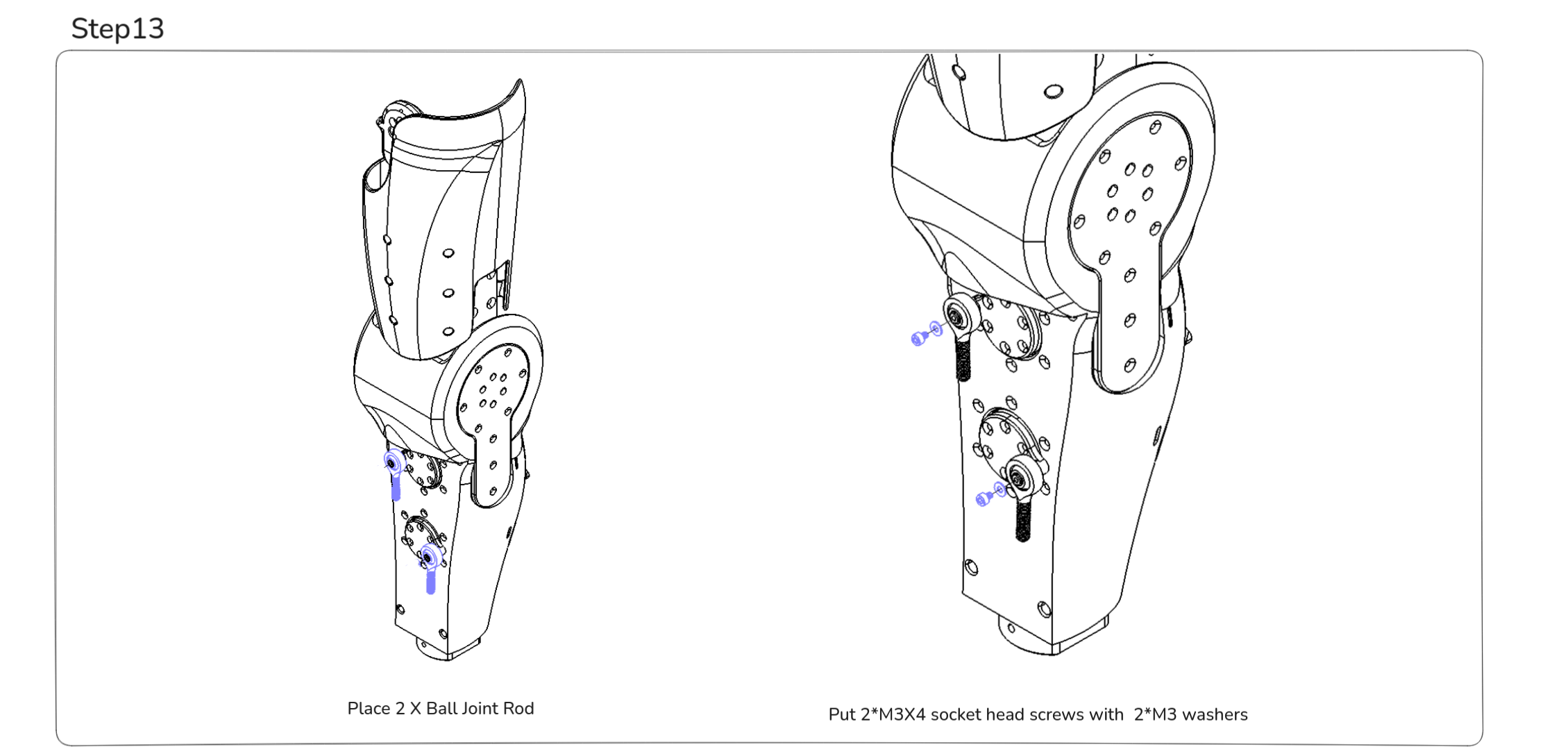
| ASV1_600_19X | 1 | Ball Joint Rod End (Right Hand), 59935K42, McMaster |
| ASV1_600_20X | 1 | Ball Joint Rod End (Right Hand), 59935K42, McMaster |
| ASV1_600_21X | 1 | Ball Joint Rod End (Right Hand), 59935K42, McMaster |
| ASV1_600_22X | 1 | Ball Joint Rod End (Right Hand), 59935K42, McMaster |
| ASV1_600_27X | 1 | 12mm Bore 1-Side, 2-Post Pillow Block, 1602-0032-0012, GoBilda |
| ASV1_600_28X | 1 | 12mm Bore 1-Side, 2-Post Pillow Block, 1602-0032-0012, GoBilda |
| ASV1_600_29X | 1 | 12mm Bore 1-Side, 2-Post Pillow Block, 1602-0032-0012, GoBilda |
| ASV1_600_30X | 1 | 12mm Bore 1-Side, 2-Post Pillow Block, 1602-0032-0012, GoBilda |
| ASV1_600_31X | 1 | 6mm D-Shaft Stainless Steel, 2101-0006-0060, GoBilda |
| ASV1_600_32X | 1 | Steel Set-Screw Collar 6mm, 2920-0001-0006, GoBilda |
| ASV1_600_33X | 1 | Steel Set-Screw Collar 6mm, 2920-0001-0006, GoBilda |
| ASV1_600_34X | 1 | 6mm Bore 1-Side, 2-Post Pillow Block, 1602-0032-0006, GoBilda |
| ASV1_600_35X | 1 | 6mm Bore 1-Side, 2-Post Pillow Block, 1602-0032-0006, GoBilda |
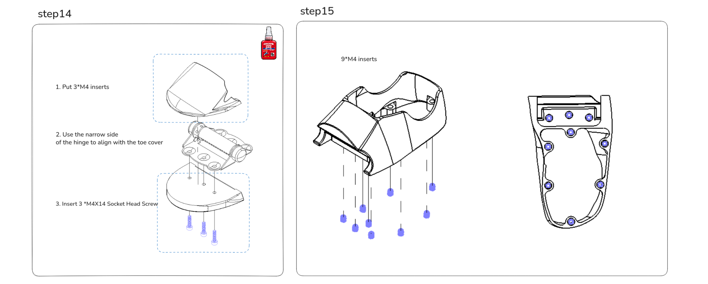
| ASV1_600_41X | 1 | Self-Closing Spring Hinge, 1481A14, McMaster |
Electronics list
| Part Number | Qty | Notes |
|---|---|---|
| ASV1_600_02X | 1 | ENCOS Motor, EC-A3814-H14-107, used for left_hip_yaw_joint (Motor ID 3) |
| ASV1_600_07X | 1 | ENCOS Motor, EC-A4315-P2-36, used for left_knee_joint (Motor ID 4) |
| ASV1_600_15X | 1 | ENCOS Motor, EC-A4310-P2-36, used for left_ankle_pitch_joint (Motor ID 5) |
| ASV1_600_16X | 1 | ENCOS Motor, EC-A4310-P2-36, used for left_ankle_roll_joint (Motor ID 6) |
Fasteners list
| Item | Qty |
|---|---|
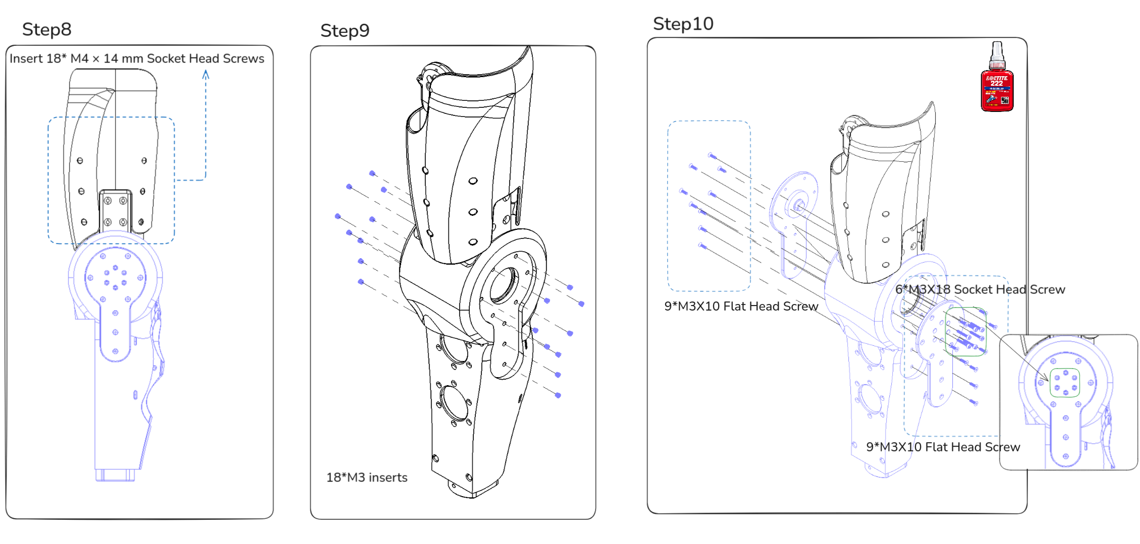
| M3 x 10 flat head screws | 18 |
| M3 x 12 flat head screws | 30 |
| M3 x 4 socket head screws | 2 |
| M3 x 6 socket head screws | 2 |
| M3 x 18 socket head screws | 6 |
| M3 x 20 socket head screws | 2 |
| M4 x 12 flat head screws | 12 |
| M4 x 10 socket head screws | 8 |
| M4 x 12 socket head screws | 3 |
| M4 x 14 socket head screws | 29 |
| M4 x 16 socket head screws | 9 |
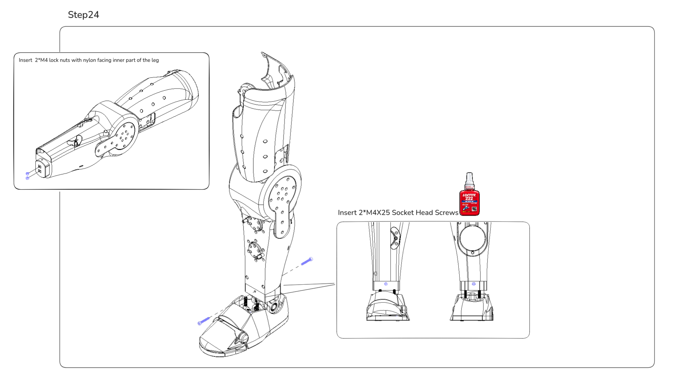
| M4 x 25 socket head screws | 11 |
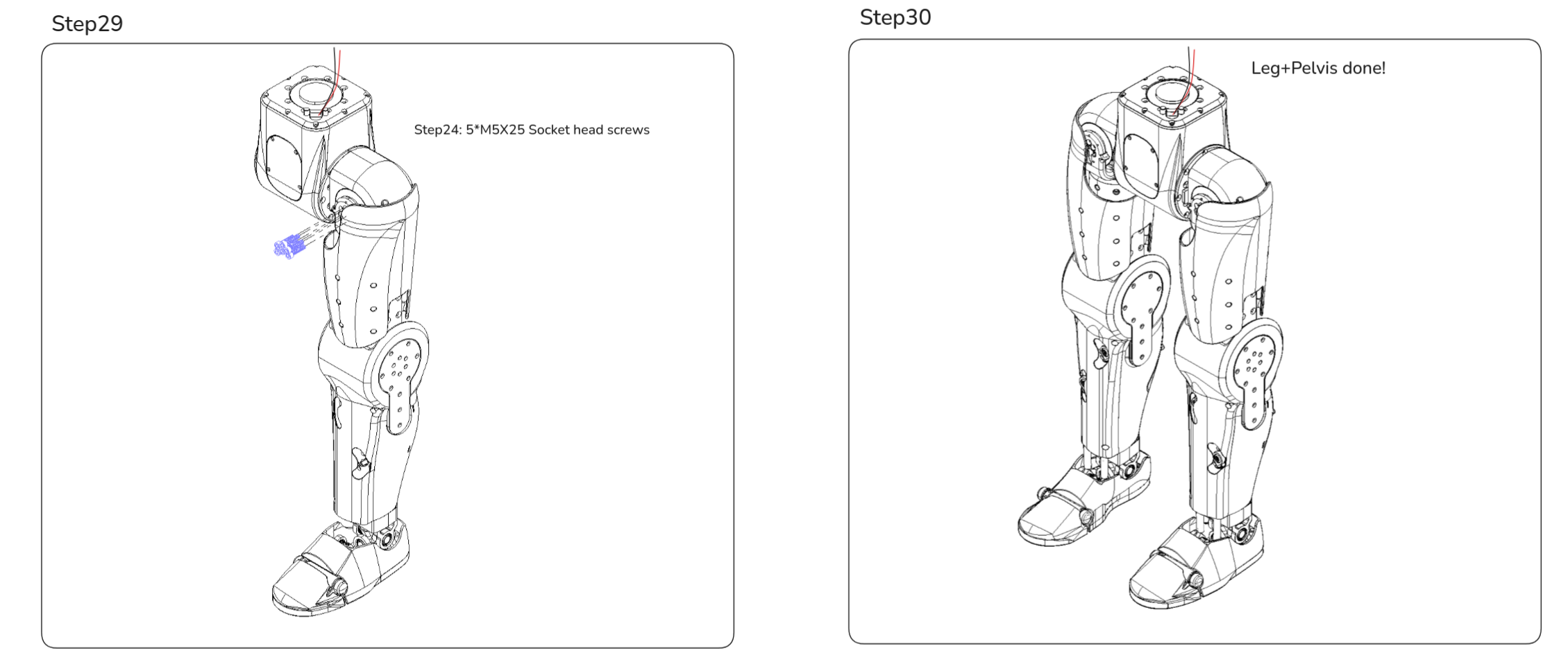
| M5 x 25 socket head screws | 5 |
| M3 inserts | 22 |
| M4 inserts | 46 |
| M4 nylon locknuts | 2 |
| M3 washers | 2 |
| M3 thread tap | 1 |
| Loctite 222 thread locker | As needed |
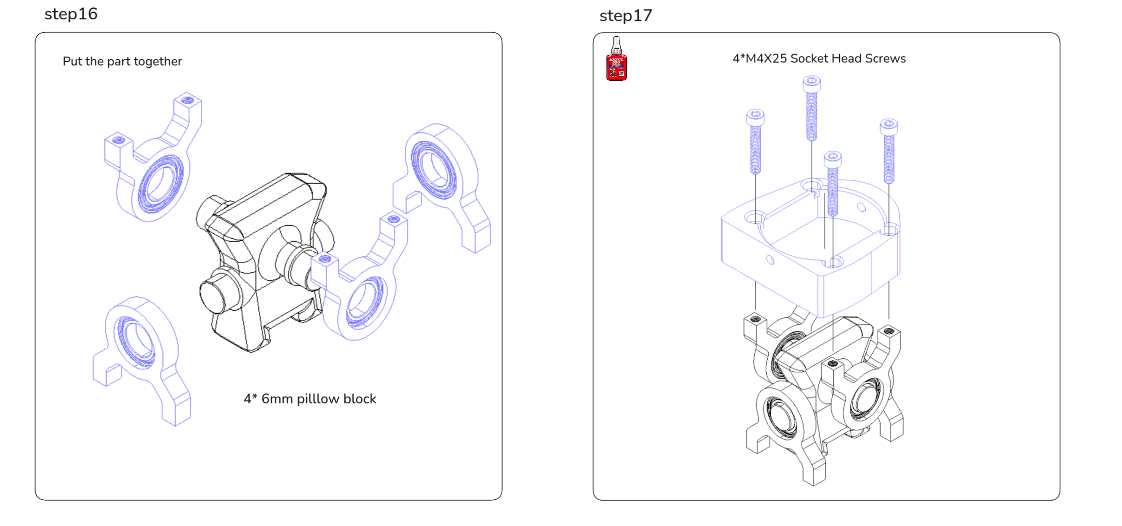
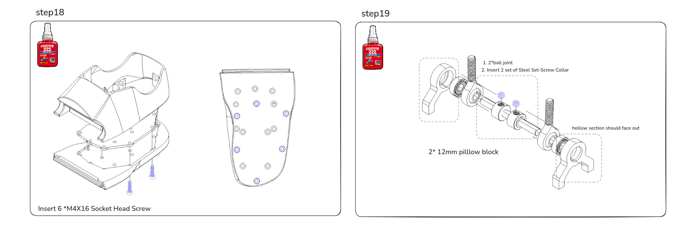
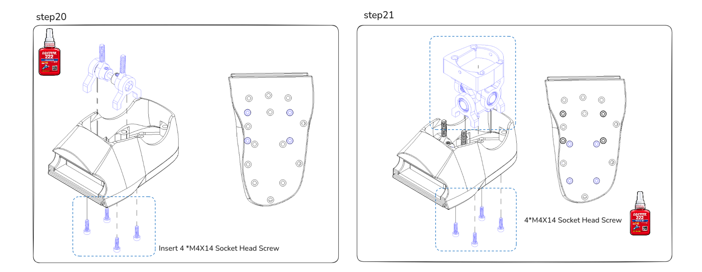
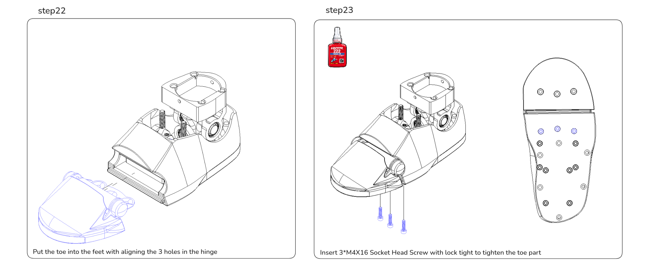
Assembly Steps
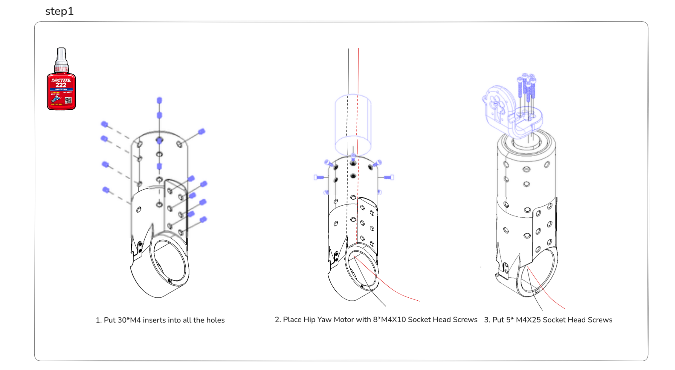
Step 1-2: Route the cable from the Hip Yaw motor shaft through the hip body, then pull it out from the bottom opening for later connection.
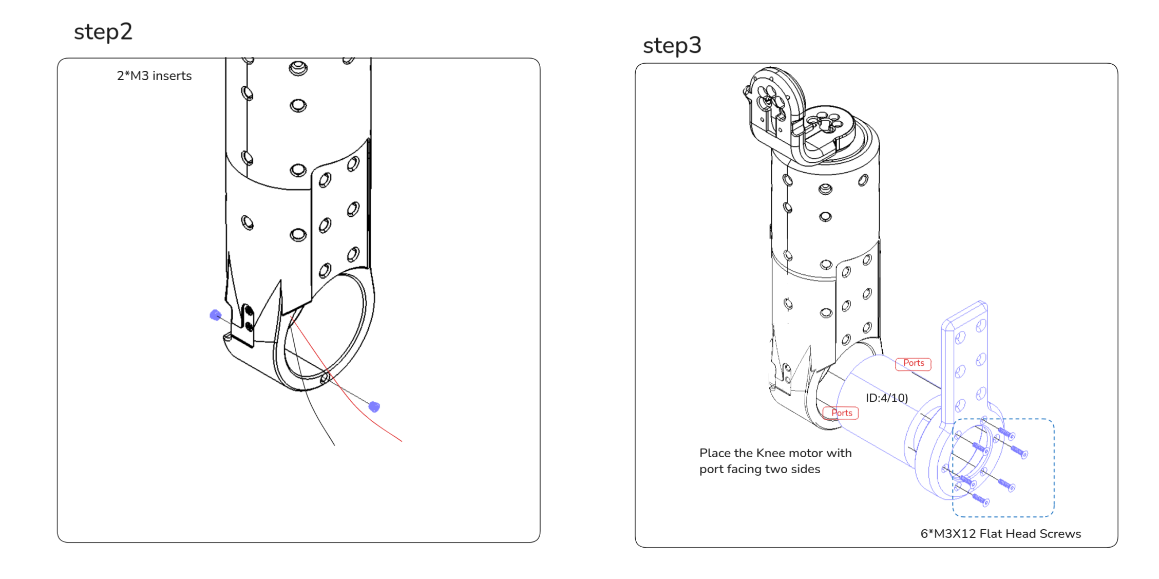
Step 3-2: Connect the pre-cut XT30(2+2) cable from the Hip Yaw motor to the Knee motor port.
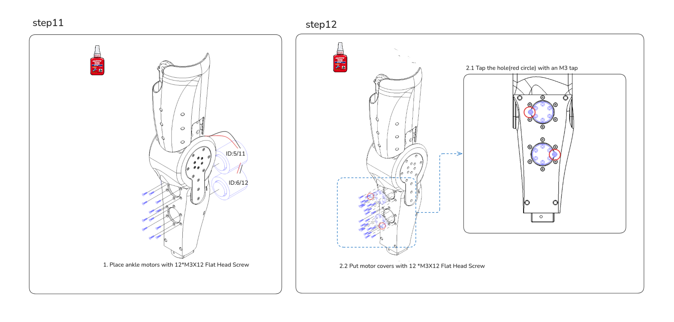 Step 11-2: Connect the XT30(2+2) cable from the Knee motor to the Ankle motors in sequence. Plug in the ankle cables first, then install the connected ankle motors together.
5. Head module 🤖
Before head assembly, set up the Raspberry Pi first. The head bring-up flow depends on the Raspberry Pi services being available.
Mechanical parts list
| Part Number | Qty | Notes |
|---|---|---|
| ASV1_700_01B | 1 | SLM 316L, As Printed |
| ASV1_700_02B | 1 | SLM 316L, As Printed |
| ASV1_700_03C | 1 | MJF PA 12, Dyeing-Dyed Black |
| ASV1_700_04C | 1 | MJF PA 12, Dyeing-Dyed Black |
| ASV1_700_05C | 1 | MJF PA 12, Dyeing-Dyed Black |
| ASV1_700_06C | 1 | MJF PA 12, Glossy Spray Paint (Brass) |
| ASV1_700_07C | 1 | MJF PA 12, Glossy Spray Paint (Brass) |
| ASV1_700_11C | 1 | MJF PA 12, Dyeing-Dyed Black |
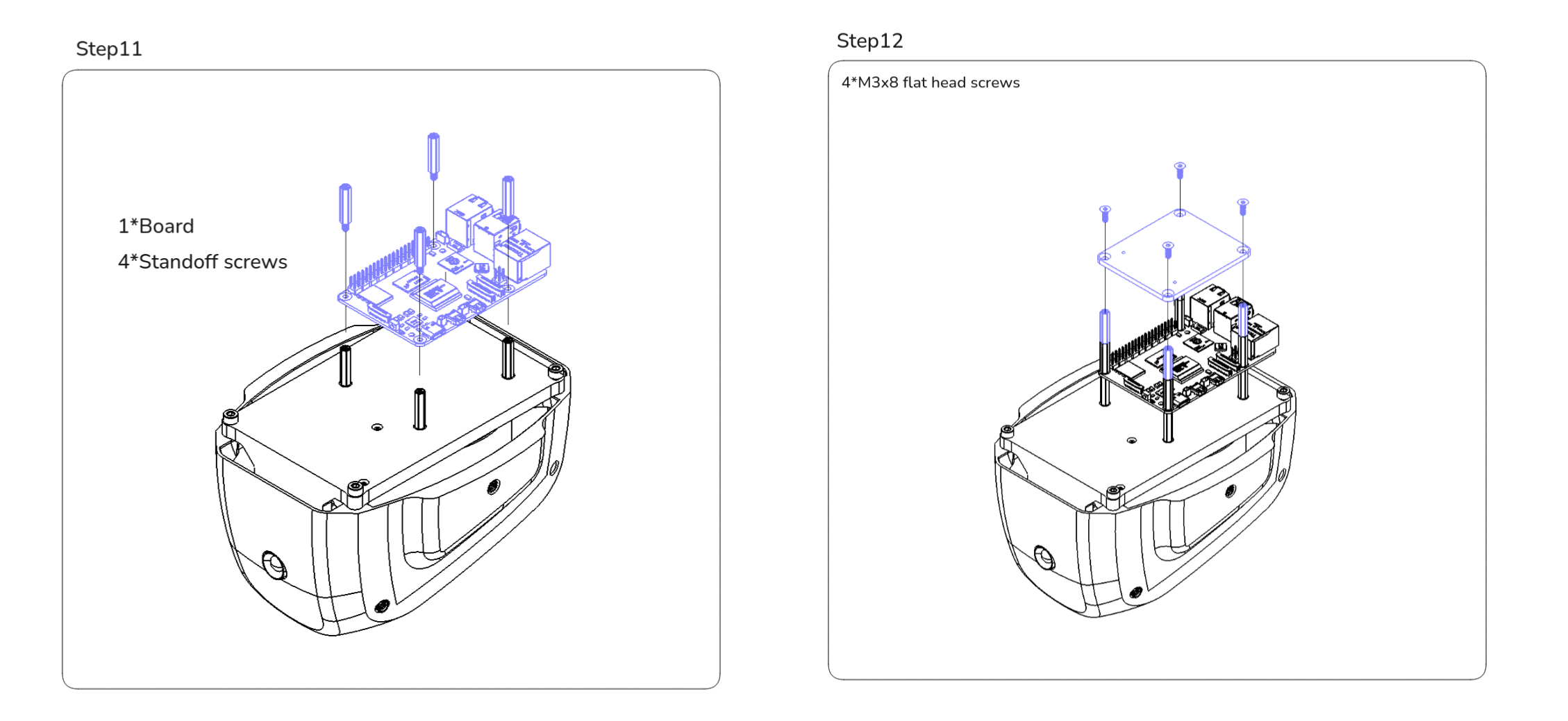
| ASV1_700_12X | 12 | Male-Female Threaded Hex Standoff, 98952A118, McMaster |
Electronics list
| Part Number | Qty | Notes |
|---|---|---|
| ASV1_700_08X | 1 | 2MP AR0230 WDR USB Camera, B0438, ArduCam |
| ASV1_700_09X | 1 | Raspberry Pi 5, Pi5, Raspberry Pi |
| ASV1_700_10X | 1 | reSpeaker USB 4-Mic Array, XVF3000 107990053, Seeed Studio |
Fasteners list
| Item | Qty |
|---|---|
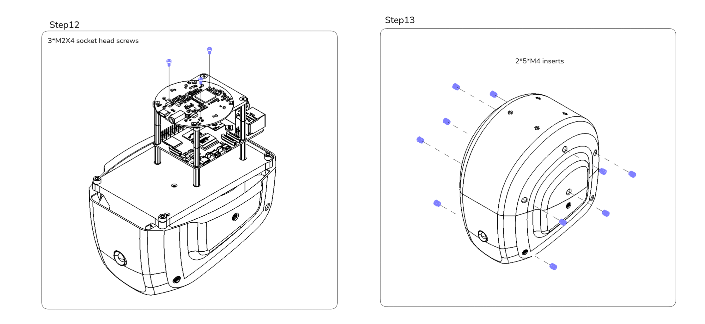
| M2 x 4 socket head screws | 3 |
| M3 x 8 flat head screws | 4 |
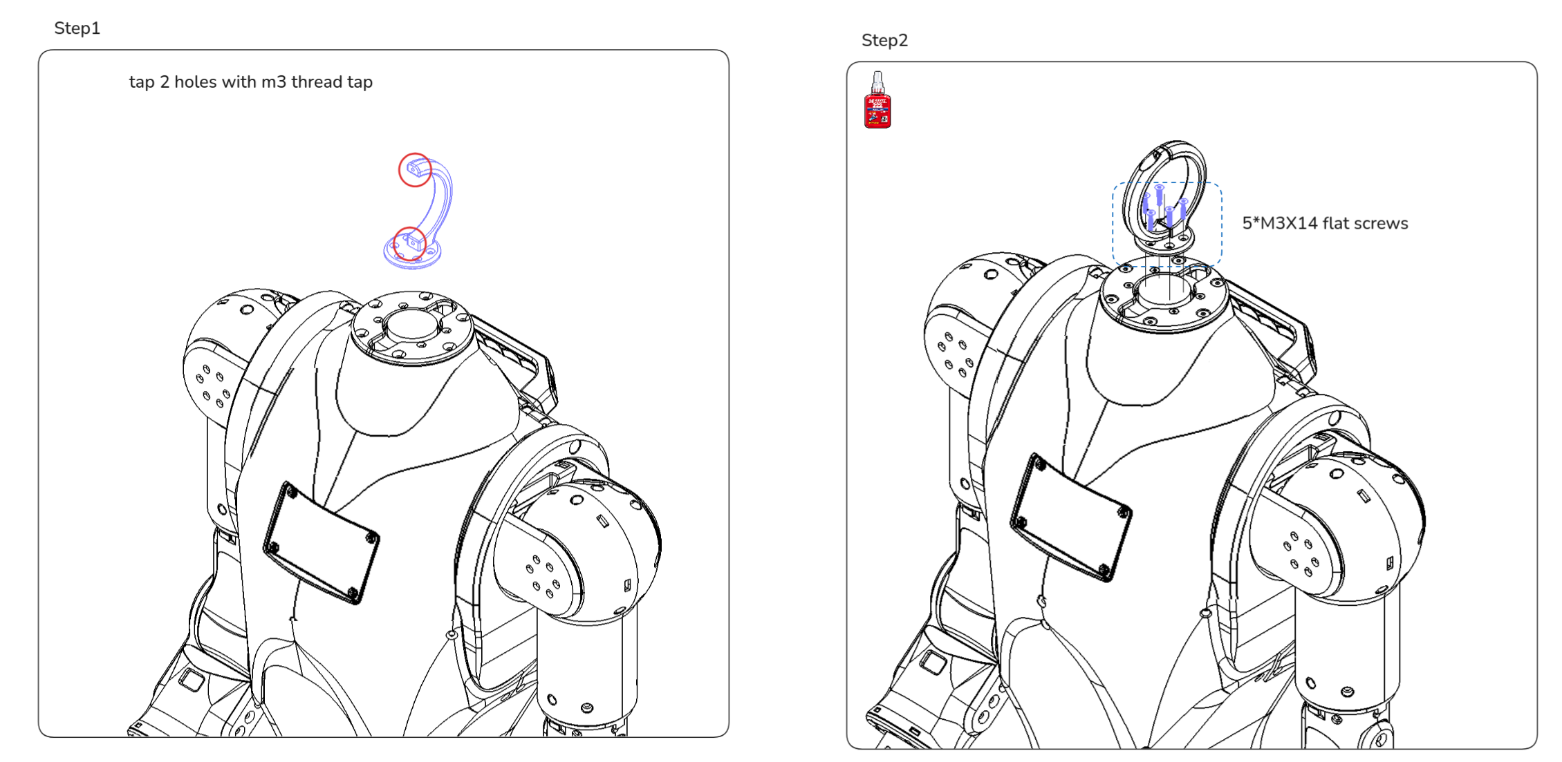
| M3 x 14 flat head screws | 5 |
| M3 x 8 socket head screws | 4 |
| M3 x 12 socket head screws | 2 |
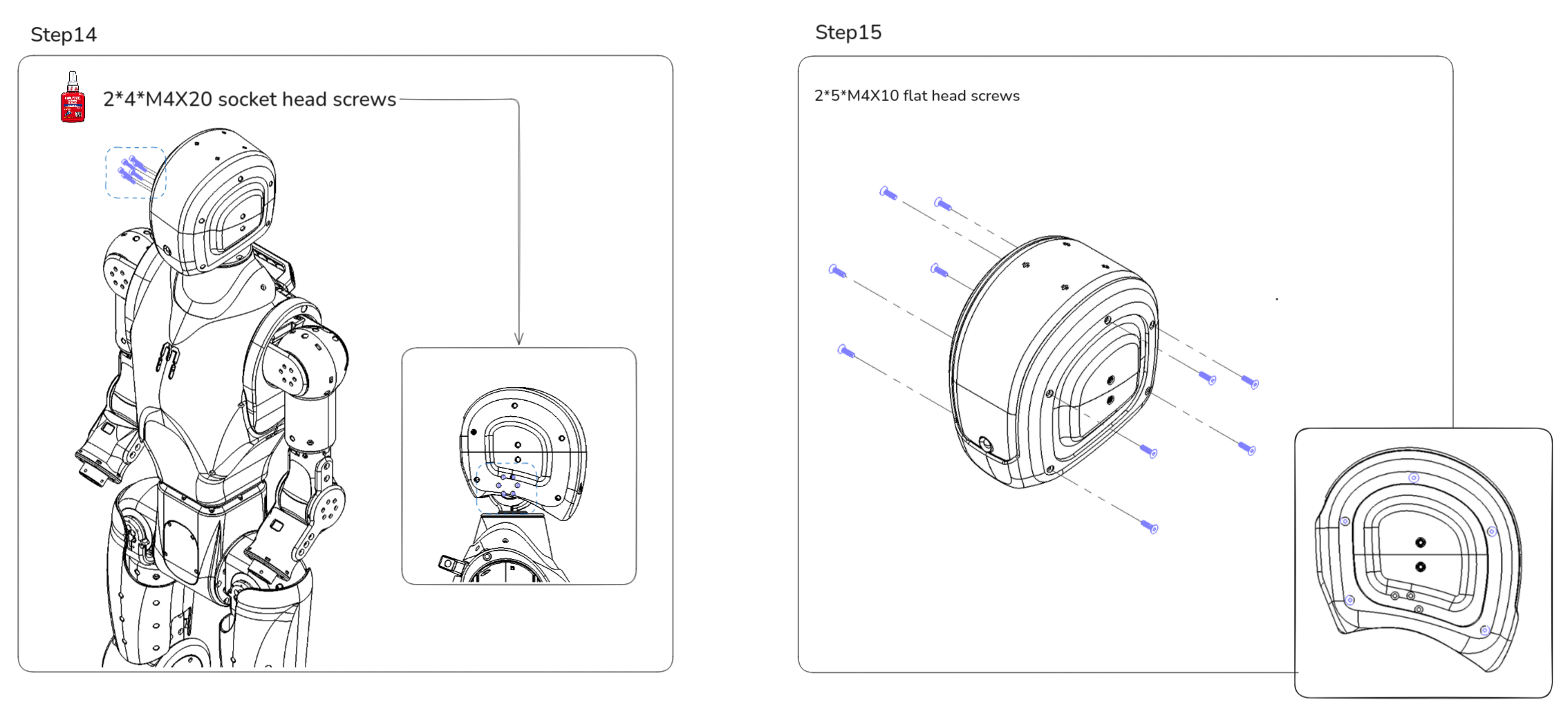
| M4 x 10 flat head screws | 10 |
| M4 x 12 socket head screws | 4 |
| M4 x 20 socket head screws | 8 |
| M2 inserts | 2 |
| M3 inserts | 8 |
| M4 inserts | 20 |
| M3 thread tap | 1 |
| Loctite 222 thread locker | As needed |
Assembly Steps
Use a separate 48 V supply during head setup. Route the required RJ45 Ethernet cables for power and communication before closing the head assembly, and connect the 3.5 mm audio cable before installing the head.
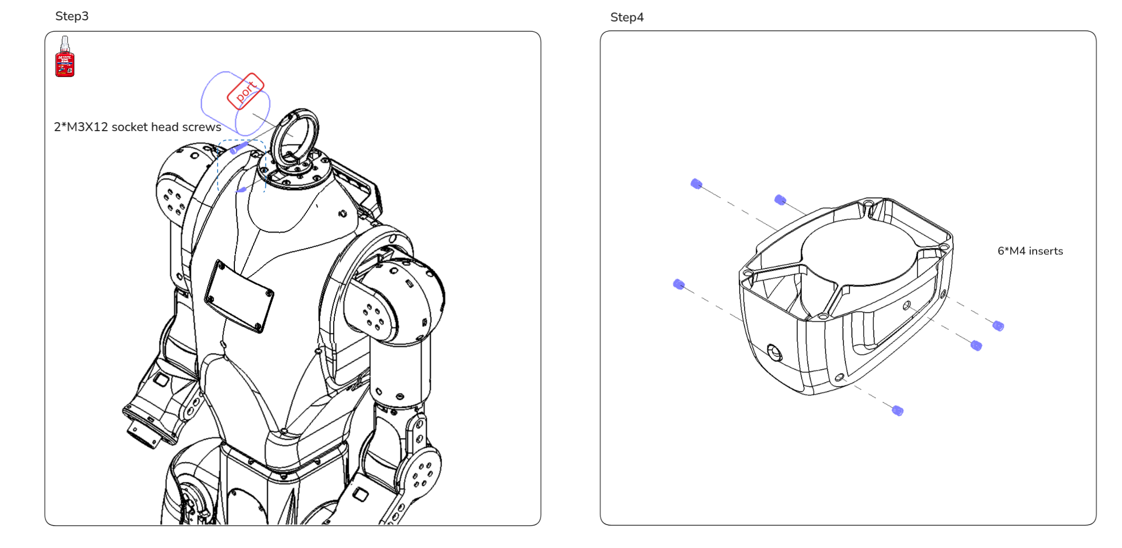
Step 31-2 Neck Yaw to Neck Pitch motor wiring: Connect the pre-cut XT30(2+2) cable from the Neck Yaw motor to the Neck Pitch motor.
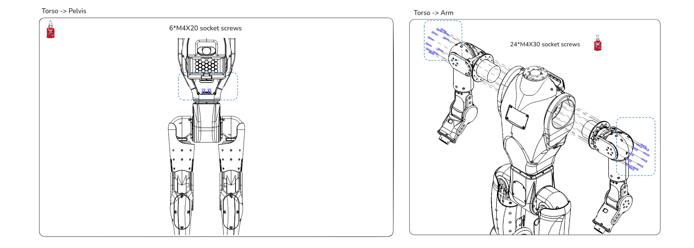
6. Connect parts:
How is this guide?