Frame and Structural Components
This chapter describes how the Asimov humanoid frame is organized, how major structural modules connect, and why the structural design choices were made.
CAD Files
You can view the STEP source file on GitHub and download it from there.
1. Asimov Humanoid Structural Architecture
The Asimov 0 legs are organized from pelvis to the ground, with 12 active degrees of freedom and 2 passive toe joints. Each leg is divided into pelvis, hip, knee, and foot modules, with 6 active DOF per leg: hip pitch, yaw, and roll; knee pitch; and ankle pitch and roll.
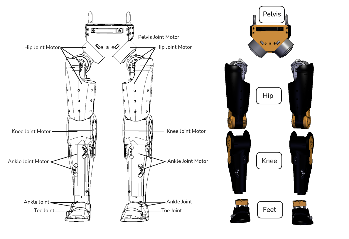
2. Structural Breakdown of Main Modules
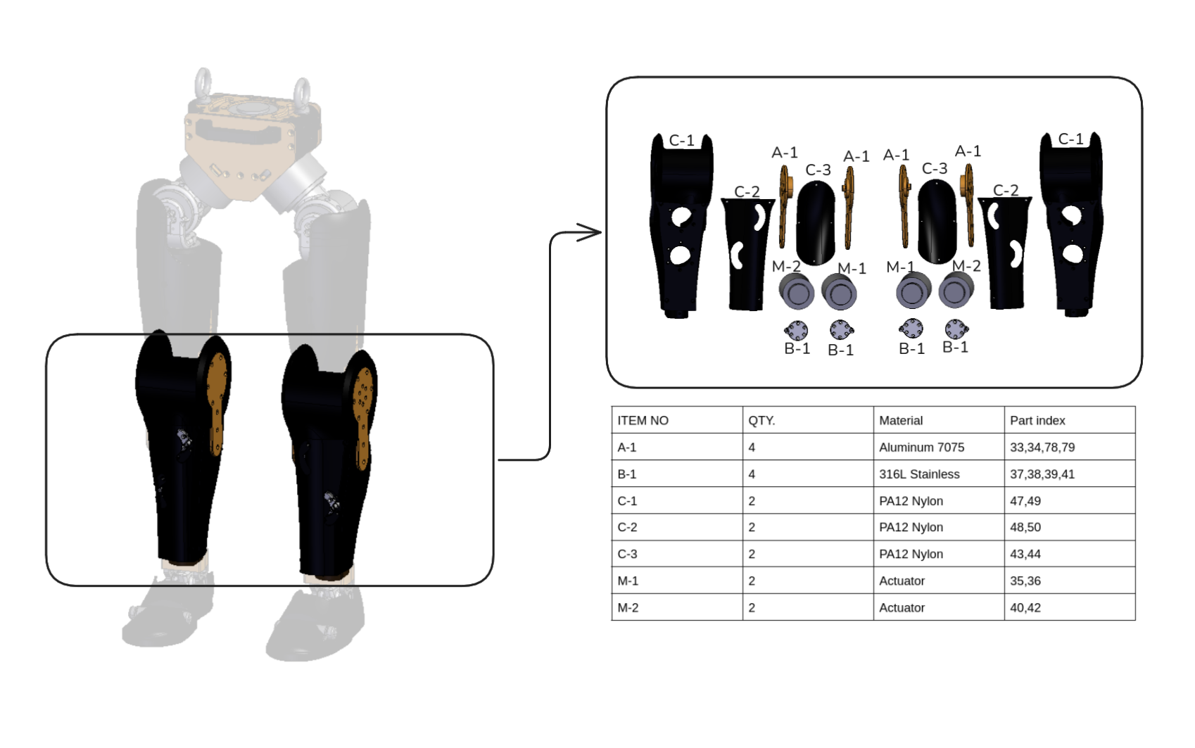
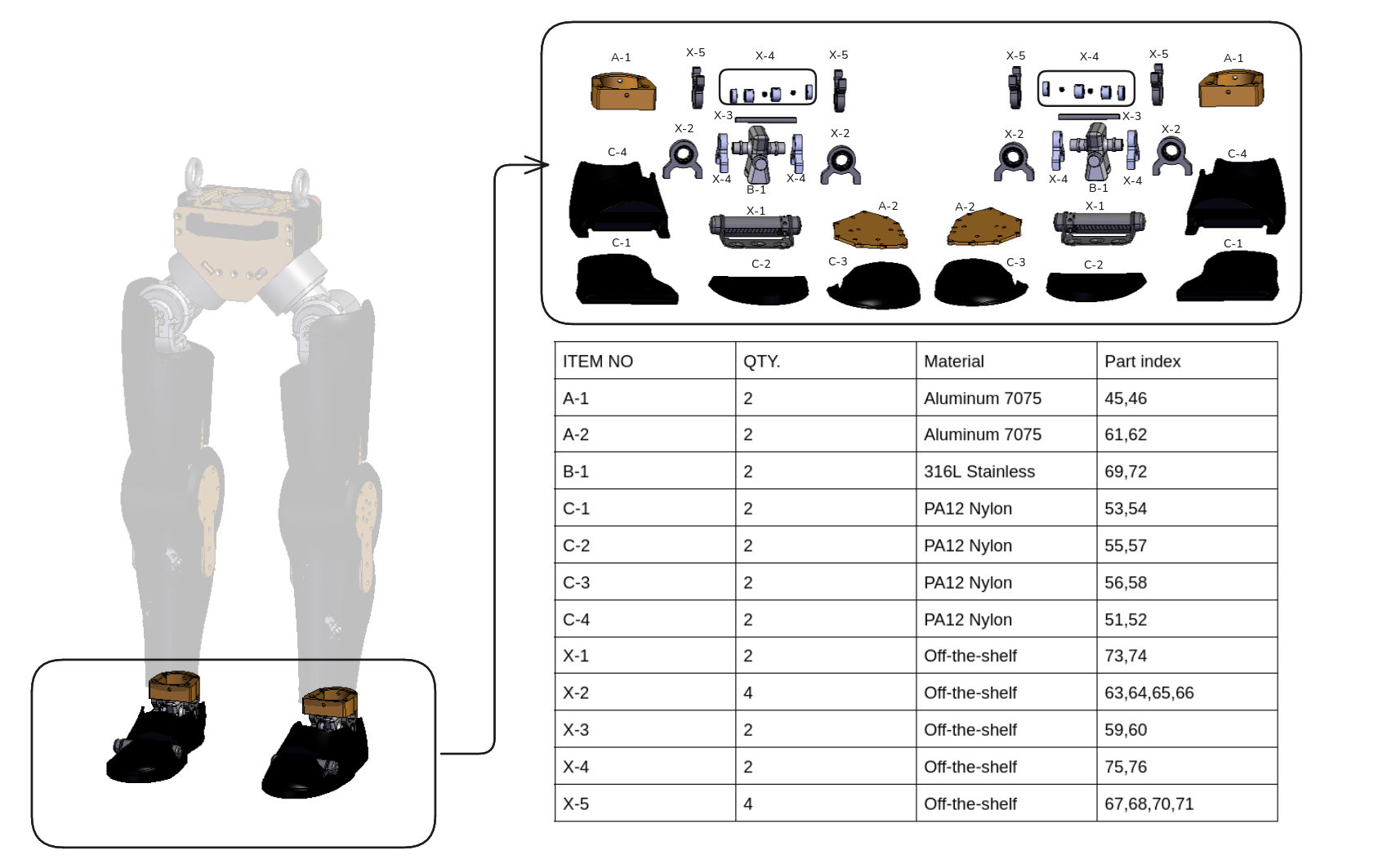
This exploded view of the Asimov 0 legs shows all parts included in the CAD files for manufacturing. Components are labeled with indices 1-79, so you can use this diagram as a checklist to confirm you have all CAD-modeled parts. Fasteners and other standard hardware (for example, screws, nuts, and washers) are not included.
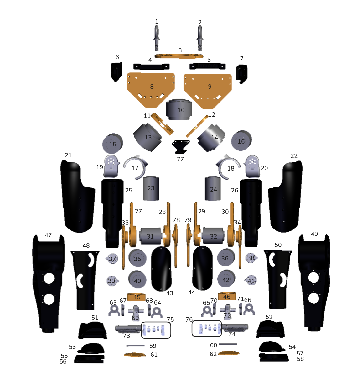 Figure: Exploded view of the legs with part index labeled.
We separate the robot this into 4 modules: Pelvis, Hip, Knee, and Feet, aligning to the assembly unit. For each section, we labaled the parts included according to their material. Also for each part we include the indexs labeled in the exploded view for a quick check.
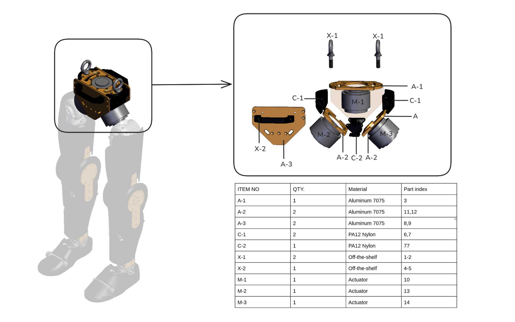
Pelvis Module
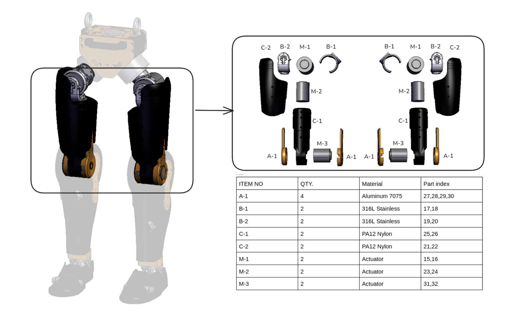
Hip Module
Knee Module
Ankle/Foot Module
3. Joint Structural Packaging
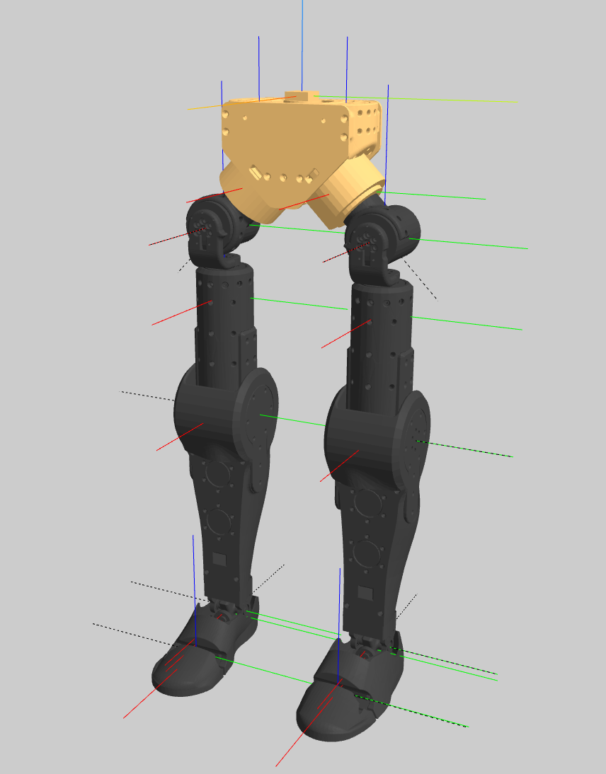
Joint Coordinate
The picture below shows the joint rotation axis with 0 joint position. The frame convention is blue for z, red for x, and green for y.
Joint Index and Joint rotation range
| Joint Index | Joint Name | Motion Range (rad) | Axis (xyz) |
|---|---|---|---|
| 1 | left_hip_pitch_joint | -2.09 ~ 1.00 | 0 0.70711 -0.70711 |
| 2 | left_hip_roll_joint | -0.79 ~ 0.79 | 1 0 0 |
| 3 | left_hip_yaw_joint | -0.79 ~ 0.79 | 0 0 -1 |
| 4 | left_knee_joint | 0.00 ~ 1.50 | 0 1 0 |
| 5 | left_ankle_pitch_joint | -0.50 ~ 0.50 | 0 1 0 |
| 6 | left_ankle_roll_joint | -0.35 ~ 0.35 | -1 0 0 |
| 7 | left_toe_joint | -0.60 ~ 0.00 | 0.010532 0.99994 0 |
| 8 | right_hip_pitch_joint | -1.00 ~ 2.09 | 0 -0.70711 -0.70711 |
| 9 | right_hip_roll_joint | -0.79 ~ 0.79 | 1 0 0 |
| 10 | right_hip_yaw_joint | -0.79 ~ 0.79 | 0 0 -1 |
| 11 | right_knee_joint | -1.50 ~ 0.00 | 0 -1 0 |
| 12 | right_ankle_pitch_joint | -0.50 ~ 0.50 | 0 -1 0 |
| 13 | right_ankle_roll_joint | -0.35 ~ 0.35 | -1 0 0 |
| 14 | right_toe_joint | 0.00 ~ 0.60 | 0.0074685 -0.99997 0 |
If you want to know more details about the joints, welcome to the next chapter Joint Design and Actuation, where we covered the actuators, ankle and toe joints design.
How is this guide?